22
english
6
Start-up and operation on a Rockwell RSLogix controller (continued)
6.4
Access to input data
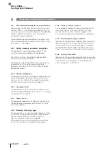
The I/O
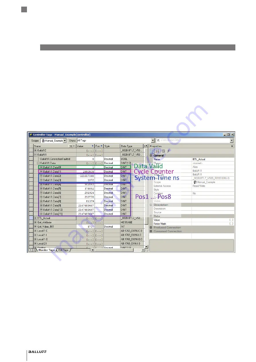
Assembly 8 x Position and Time
is selected in the
example.
The first four DINT values contain the validity flag (
Data
Valid
), the cycle counter (
Cycle Counter
) and the system
time in ns (
System Time ns
, divided between two DINT).
Eight position values follow. Because only five magnets are
parameterized, the last three magnets (Balluff:I1.Data[9] …
[11]) are set to the error value (2147483647 =
0x7FFFFFFF). Magnet 1 (Balluff:I1.Data[4]) has the highest
and magnet 5 (Balluff:I1.Data[8]) the lowest position value
due to the inverted measurement direction.
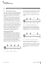
Furthermore, an array BTL_Actual is set up as an alias for
Balluff:I1, which allows access to the data via an array.
BTL7-V50D-…
Configuration Manual
Summary of Contents for Ethernet/IP BTL7-V50D Series
Page 1: ...BTL7 V50D Konfigurationshandbuch deutsch...
Page 2: ...www balluff com...
Page 36: ...BTL7 V50D Configuration Manual english...
Page 37: ...www balluff com...

