6
STARTUP
59
www. matrix-vision.com
BVS SC-_1280Z00-30-0-0
SMART
CAMERA
Fieldbus
www.balluff.com
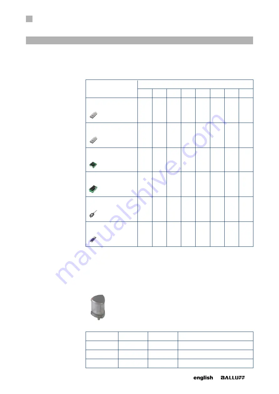
Device class 1: IO-Link I/O modules
The 8 I/O channels are linked with pin 4 of the ports of the I/O modules (or with the first 8
I/O lines). The function of the individual pins depends on the configuration of the I/O
channels (input or output).
SMARTCAMERA
I/O 0
I/O 1
I/O 2
I/O 3
I/O 4
I/O 5
I/O 6
I/O 7
BNI005L
BNI IOL-302-000-K006
Port
0,4
1)
Port
1,4
Port
2,4
Port
3,4
Port
4,4
Port
5,4
Port
6,4
Port
7,4
BNI007Z
BNI IOL-302-002-K006
Port
0,4
1)
Port
1,4
Port
2,4
Port
3,4
Port
4,4
Port
5,4
Port
6,4
Port
7,4
BNI004L
BNI IOL-310-000-K025
IO1
IO2
IO3
IO4
IO5
IO6
IO7
IO8
BNI004K
BNI IOL-309-000-K024
IO1
IO2
IO3
IO4
IO5
IO6
IO7
IO8
BNI005M
BNI IOL-771-000-K027
IO1
IO2
IO3
IO4
IO5
IO6
IO7
IO8
BNI003A
BNI IOL-302-S01-Z013
Port
0,4
Port
1,4
Port
2,4
Port
3,4
Port
4,4
Port
5,4
Port
6,4
Port
7,4
1)
The representation 0,4 means port 0, pin 4.
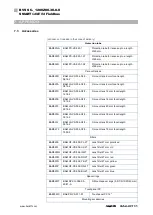
Some of these I/O modules require a voltage supply for actuators at pin 2 of the IO-Link
connection. For details, see the manual of the respective device. The
SMARTCAM-
ERA
provides the actuator supply. The connection must be made with a 4-conductor
cable.
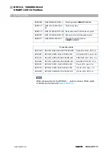
Device class 2: SMARTLIGHT
•
BNI007T BNI IOL-800-000-Z036 (1-stage)
The 1-stage
SMARTLIGHT
is controlled with the IO channels I/O5, I/O 6 and I/O 7.
I/O 5
I/O 6
I/O 7
Description
0
0
0
Off
1
0
0
Red
0
1
0
Yellow


