background image

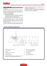
CARATTERISTICHE COSTRUTTIVE

• 

Testa di combustione Low NOx a ricircolo interno, completa di boc

-

caglio in acciaio inox.

•  Ventilatore centrifugo per alte prestazioni.

•  Flangia d'attacco al generatore scorrevole per adattare la sporgen-

za della testa ai vari tipi di generatori di calore.

•  Parte ventilante in lega leggera d'alluminio.

• 

Convogliatore con serranda di regolazione portata aria comburen

-

te.

• 

Presa a 7 poli per l’alimentazione elettrica e termostatica del bru

-

ciatore, presa a 4 poli per il comando del secondo stadio di funzio-

namento.

• 

Pressostato aria che assicura la presenza dell'aria comburente.

•  Chiusura della serranda aria in sosta per evitare dispersioni di calo-

re al camino attraverso il servomotore regolazione aria.

•  Rampa gas principale in versione CE composta da valvola di fun-

zionamento e di sicurezza ad azionamento elettromagnetico, pres-

sostato di minima, regolatore di pressione e filtro gas.

• 

Possibilità di integrare il bruciatore con un kit per il controllo tenuta 

valvole.

•  Connessione alla rampa gas con connettori a prova d'errore

• 

Oblò visualizzazione fiamma.

•  Motore elettrico trifase per l'azionamento del ventilatore.

• 

Controllo della presenza di fiamma tramite elettrodo ionizzatore.

• 

Apparecchiatura automatica di comando e controllo del bruciatore.

•  Quadro comandi comprendente interruttori marcia/arresto - auto-

matico / manuale - selettore minimo / massimo, spie di funziona-

mento e di blocco.

• 

Regolazione portata combustibile / aria comburente mediante ser

-

vomotore comandato dall’apparecchiatura.

CARATTERISTICHE TECNICO FUNZIONALI

• 

Per aumentare la durata dell'apparecchio è da preferirsi un am

-

biente  d'installazione  aerato  e  con  temperatura  sufficientemente 

contenuta;

•  Funzionamento a due stadi progressivi o modulante.

• 

Bruciatore di gas a basse emissioni di NOx e CO secondo "Classe 

III della normativa europea EN676".

• 

Manutenzione facilitata dalla possibilità di sfilare il gruppo di misce

-

lazione senza smontare il bruciatore dalla caldaia.

•  Regolazione della portata minima e massima dell’aria e del gas 

tramite modulatore con camma meccanica azionato da servomo-

tore elettrico.

• 

Possibilità di ottenere ottimi valori di combustione tramite la regola

-

zione dell'aria comburente e della testa di combustione.

ITALIANO

10 / 34

0006160254_202001

Summary of Contents for TBG 80 LX MC

Page 1: ...STAGE GAS BURNERS ITALIANO Manuale istruzioni per l installazione l uso e la manutenzione IT Instruction manual for installation use and maintenance EN TBG 80 LX MC TBG 110 LX MC TBG 140 LX MC TBG 20...

Page 2: ......

Page 3: ...one del funzionamento 15 Descrizione del funzionamento della modulazione 15 Controllo tenuta valvole VPS 504 se presente 16 Regolazione aria sulla testa di combustione 17 Accensione e regolazione 17 M...

Page 4: ...E GENERALI La data di produzione dell apparecchio mese anno sono indicati sulla targa identificazione bruciatore presente sull apparecchio L apparecchio non adatto a essere usato da persone bambini co...

Page 5: ...cue quelle parti che potrebbero essere potenziali fonti di pericolo AVVERTENZE PER L AVVIAMENTO IL COLLAUDO L USO E LA MANUTENZIONE L avviamento il collaudo e la manutenzione devono essere effet tuati...

Page 6: ...condi zione della categoria di sovratensione III Sguainare l isolante esterno del cavo di alimentazione nella misura strettamente necessaria al collegamento evitando cos che il filo possa venire a co...

Page 7: ...se 3 Classe 3 Motore ventola 50hz kW 1 1 1 5 2 2 3 Motore ventola 60hz kW 1 1 1 5 2 6 3 5 Potenza elettrica assorbita 50hz kW 1 4 2 2 6 3 5 Potenza elettrica assorbita 60hz kW 1 4 2 3 4 Tensione di al...

Page 8: ...prodotto 4 Modello bruciatore 5 Matricola 6 Potenza combustibili liquidi 7 Potenza combustibili gassosi 8 Pressione combustibili gassosi 9 Viscosit combustibili liquidi 10 Potenza motore ventilatore 1...

Page 9: ...ERMICA MIN PROPANO TBG 80 LX 200 kW IMPORTANTE I campi di lavoro sono ottenuti su caldaie di prova rispondenti alla norma EN676 e sono orientativi per gli accoppiamenti bruciatore caldaia Per il corre...

Page 10: ...cco rampa gas TBG 360 MC 6 Quadro elettrico 7 Motore 8 Servomotore regolazione aria gas 9 Targa identificazione bruciatore 8 7 9 1 3 4 6 2 5 6 1 0002471570N1 10 QUADRO ELETTRICO 1 Apparecchiatura 2 Pr...

Page 11: ...320 370 550 380 170 200 1280 TBG 140 LX MC 690 320 370 550 380 170 200 1280 TBG 200 LX MC 690 320 370 550 380 170 200 1280 Modello D E F I L M N TBG 80 LX MC 175 400 180 178 280 250 325 M12 190 TBG 11...

Page 12: ...onnettori a prova d errore Obl visualizzazione fiamma Motore elettrico trifase per l azionamento del ventilatore Controllo della presenza di fiamma tramite elettrodo ionizzatore Apparecchiatura automa...

Page 13: ...iatore Per ottenere il miglior funzionamento del regolatore di pressione opportuno che sia applicato sulla tubazione orizzontale dopo il filtro Il regolatore di pressione del gas deve essere regolato...

Page 14: ...aldaia MONTAGGIO RAMPA GAS Sono possibili diverse soluzioni di montaggio 8 8a della rampa gas PERICOLO ATTENZIONE Con valvola di dimensioni notevoli esempio DN65 oppure DN80 prevedere un adeguato supp...

Page 15: ...te elettrica come previsto dalle normative di sicurezza vigenti Per i collegamenti elettrici linea e termostati vedere il relativo schema elettrico Sguainare l isolante esterno del cavo di alimentazio...

Page 16: ...trasparente sul quadro procedere posizionando i ganci in corrispondenza delle ri spettive sedi 9 far scorrere lo sportellino nella direzione indicata dalla freccia e riavvitare le viti 10 CAUTELA AVV...

Page 17: ...to e il completamento della fase di accensione con disinserzione del trasformatore Successivamente si verifica il passaggio al secondo stadio di potenza mediante apertura progressiva della farfalla ga...

Page 18: ...ssione a monte Volendo effettuarne la verifica inserire un manometro in corrispon denza della presa di pressione PA Se il ciclo di prova ha esito positivo dopo alcuni secondi si accende la lampada di...

Page 19: ...46 1 5 TBG 200 LX MC 14 51 1 5 Allentare la vite 1 Agire sulla vite 2 per posizionare la testa di combustione 3 rife rendosi all indice 4 Regolare la distanza x tra il valore minimo e massimo secondo...

Page 20: ...sia contrastata dalla corrente di scarica del trasformatore di accensione le due correnti hanno un percorso in comune sulla massa del bruciatore pertan to il bruciatore si porta in blocco per insuffic...

Page 21: ...re d accensione e non si aprono le valvole del gas e di conseguenza il bruciatore si arresta in blocco Sbloccare il bruciatore premendo l apposito pulsante e riportare la regolazione del pressostato a...

Page 22: ...funzionamento dell apparecchiatura riportato nello schema elettrico specifico Terminata la misurazione ripristinare il ponticello in precedenza scollegato 0002935021 TBG 110 LX P LX PN V TBG 110 LX M...

Page 23: ...di il pulsante di sblocco un lampeggio veloce di colore rosso indicher che la funzione attiva analogamente per disattivare la funzione baster premere per almeno 3 secondi il pulsante di sblocco la com...

Page 24: ...vole combustibile Malfunzionamento rilevatore fiamma Difettosit nella taratura del bruciatore assenza di combustibile Mancata accensione difettosit trasformatore di accensione 3 lampeggi On Malfunzion...

Page 25: ...cipale HS Contatto ausiliario rel ION Sonda di Ionizzazione K1 4 Rel Interni KL Fiamma bassa LK Serranda dell Aria LKP Posizione della serranda dell aria LP Pressostato aria LR Modulazione M Motore ve...

Page 26: ...I V Camma trasformatore accensione 40 Camma V IV Circa 5 10 1 Perno inserzione ed esclusione accoppiamento motore albero camme 2 Scala di riferimento 3 Indicatore di posizione 4 Camme regolabili Per m...

Page 27: ...PN V TBG 200 LX ME LX MC TBG 260 LX ME TBG 360 LX ME TBG 80 LX P LX PN V TBG 80 LX ME LX MC A A A B B B 1 1 1 1 1 1 2 2 2 2 2 2 3 3 3 4 4 4 5 5 5 C A B TBG 80 LX MC 5 8 TBG 110 LX MC 5 5 TBG 140 LX MC...

Page 28: ...on deformati e privi di impurit o depositi derivanti dall ambiente di installazione e o da una cattiva combustione Per la pulizia della testa di combustione necessario smontare la bocca nei suoi compo...

Page 29: ...AGGIO PATTINO E VITI ANNO LEVE TIRANTI SNODI SFERICI CONTROLLO EVENTUALI USURE LUBRIFICAZIONE COMPONENTI ANNO IMPIANTO ELETTRICO VERIFICA CONNESSIONI E SERRAGGIO MORSETTI ANNO INVERTER PULIZIA VENTOLA...

Page 30: ...na o di pagamento sono indipendenti e non fanno riferi mento alla vita attesa di seguito indicata Per condizioni operative normali si intendono applicazioni su caldaie ad acqua e generatori di vapore...

Page 31: ...cazione naturale da batteria di bombole o serbatoio utilizzabile solo per impianti di piccola potenza La capacit di erogazione in fase di gas in funzione delle dimensioni del serba toio e della temper...

Page 32: ...lizzatore Riduttore di 2 salto Uscita 30 hPa mbar Portata il doppio del massimo richiesto dall utilizzatore Filtro a Y Filtro Filtro Presa di pressione Riduttore di 2 salto Uscita 30 hPa mbar Portata...

Page 33: ...ata dall aria caso di prima accensione 3 La pressione del gas insufficiente o eccessiva 4 Passaggio aria tra disco e testa troppo chiuso RIMEDIO 1 Invertire l alimentazione lato 230V del trasformatore...

Page 34: ...SCHEMI ELETTRICI ITALIANO 32 34 0006160254_202001...

Page 35: ...NTAORE PA PRESSOSTATO ARIA Pm PRESSOSTATO DI MINIMA S1 INTERRUTTORE MARCIAARRESTO S2 PULSANTE SBLOCCO S4 SELETTORE AUT MAN S5 COMMUTATORE MIN O MAX SG INTERRUTTORE GENERALE T2 TERMOSTATO 2 STADIO TA T...

Page 36: ...ITALIANO 34 34 0006160254_202001...

Page 37: ...cription 15 Modulation operation description 15 VPS 504 valve tightness control if present 16 Air regulation on the combustion head 17 Starting up and regulation 17 Ionisation current measurement 20 C...

Page 38: ...etween 25 C and 55 C The storage time is 3 years GENERAL WARNINGS The equipment production date month year is written on the bur ner identification plate located on the equipment The equipment cannot...

Page 39: ...main switch Cut off the fuel supply using the shut off valve and remove the control wheels from their position Render harmless any potentially dangerous parts WARNINGS FOR START UP TEST USE AND MAINT...

Page 40: ...ove the external insulating seal of the supply pipe necessary for the connection preventing the cable to touch metal parts The use of any electrically fed components entails complying with certain fun...

Page 41: ...pane emissions mg kWh Class 3 Class 3 Class 3 Class 3 50hz fan motor kW 1 1 1 5 2 2 3 60hz fan motor kW 1 1 1 5 2 6 3 5 Absorbed electrical power 50hz kW 1 4 2 2 6 3 5 Absorbed electrical power 60hz k...

Page 42: ...16 15 1 Company logo 2 Company name 3 Product code 4 Burner model 5 Serial number 6 Liquid fuel power 7 Gaseous fuel power 8 Gaseous fuel pressure 9 Liquid fuel viscosity 10 Fan motor power 11 Power s...

Page 43: ...IMPORTANT MINIMUM PROPANE THERMAL POWER TBG 80 LX 200 kW IMPORTANT The operating ranges are obtained from test boilers corresponding to Standard EN676 and are indicative of the burner boiler combinat...

Page 44: ...connector flange TBG 360 MC 6 Electrical panel 7 Motor 8 Air gas regulation servomotor 9 Burner identification plate 8 7 9 1 3 4 6 2 5 6 1 0002471570N1 10 ELECTRICAL PANEL 1 Control box 2 Air pressur...

Page 45: ...0 370 550 380 170 200 1280 TBG 140 LX MC 690 320 370 550 380 170 200 1280 TBG 200 LX MC 690 320 370 550 380 170 200 1280 Model D E F I L M N TBG 80 LX MC 175 400 180 178 280 250 325 M12 190 TBG 110 LX...

Page 46: ...ain with fail safe connectors Flame inspection glass Three phase electric motor to run fan Flame detection by means of ionisation electrode Automatic burner control and command equipment Control panel...

Page 47: ...ensure optimal functioning of the pressure regulator it should be applied to the horizontal pipe after the filter The gas pressure regulator must be regulated when the burner is working at the maximu...

Page 48: ...able material ASSEMBLING THE GAS TRAIN The gas train can be assembled in different ways 8 8a DANGER ATTENTION In case of very large valves e g DN65 or DN80 make sure there is a suitable support to pre...

Page 49: ...e 3 mm in accordance with current safety regulations Refer to the wiring diagram for electrical connections line and ther mostats Remove the external insulating seal of the supply pipe necessary for t...

Page 50: ...ansparent door on the panel properly position the hooks at their hooking points 9 slide the door in the direction indicated by the arrow and tighten the screws again 10 CAUTION WARNINGS Only professio...

Page 51: ...nd completion of ignition turning off the transformer Then passing on to the second stage of power through the progres sive opening of the gas throttle and the air damper at the same time At the momen...

Page 52: ...carry out a check place a pressure gauge correspon ding to the PA pressure plug If the test circuit has a positive result the LC authorisation lamp yel low switches on after a few seconds In order to...

Page 53: ...40 LX MC 10 46 1 5 TBG 200 LX MC 14 51 1 5 Loosen the screw 1 Turn screw 2 to position the combustion head 3 referring to index 4 Adjust the distance x between the minimum and maximum accor ding to th...

Page 54: ...on current is disturbed by the dischar ge current of the ignition transformer the two currents have a com mon path on the burner s mass so the burner locks out due to an insufficient ionisation Invert...

Page 55: ...s valves and so the burner locks out To unlock the burner press the special push button and return the pressure switch regulator to a value sufficient for measuring an air pressure slightly below the...

Page 56: ...the equipment is shown in the specific wiring diagram At the end of the measurement connect the jumper that has been disconnected 0002935021 TBG 110 LX P LX PN V TBG 110 LX ME LX MC TBG 140 LX P PN V...

Page 57: ...or at least 3 seconds A quick red flashing indicates that the function is active Likewise hold the reset button down for at least 3 seconds to deactivate the function the switching will be indicated w...

Page 58: ...n No flame at the end of the safe ignition time TSA Fuel valves malfunctioning Flame detector malfunctioning Incorrect burner calibration no fuel No ignition faulty ignition transformer 3 blinks On Fa...

Page 59: ...Auxiliary contactor relay ION__tab_Ionisation probe K1 4 Internal Relays KL Low flame LK Air damper LKP Air damper position LP Air pressure switch LR Modulation M Fan motor MS Synchronous motor NL Ra...

Page 60: ...air cam 30 IV III V Ignition transformer cam 40 Cam V IV Approx 5 10 1 Motor camshaft coupling On Off pin 2 Reference scale 3 Position indicator 4 Adjustable camshaft Use the corresponding rings to mo...

Page 61: ...P LX PN V TBG 200 LX ME LX MC TBG 260 LX ME TBG 360 LX ME TBG 80 LX P LX PN V TBG 80 LX ME LX MC A A A B B B 1 1 1 1 1 1 2 2 2 2 2 2 3 3 3 4 4 4 5 5 5 C A B TBG 80 LX MC 5 8 TBG 110 LX MC 5 5 TBG 140...

Page 62: ...e not been deformed and are free from deposits deriving from the installation environment and or from poor combustion In order to clean the combustion head its outlet components must be disassembled B...

Page 63: ...CK OF WEAR AND OPERATION GREASING OF SLIDING BLOCK AND SCREWS YEAR LEVERS TIE RODS BALL JOINTS CHECK OF ANY WEAR COMPONENT LUBRICATION YEAR ELECTRICAL SYSTEM CHECK OF CONNECTIONS AND TERMINAL TIGHTENI...

Page 64: ...contracts and or delivery or payment notes if necessary are independent and do not refer to the expected lifespan stated below Normal operating conditions means applications on water boilers and stea...

Page 65: ...safe operation bb Natural gasification from sets of cylinders or a tank can be used only in low power systems Gas supply capacity on the basis of tank size and minimum outdoor temperature are shown in...

Page 66: ...red by the user 2nd step reducer Output 30 hPa mbar Flow rate double the maximum required by the user Y filter Filter Filter Pressure intake 2nd step reducer Output 30 hPa mbar Flow rate double the ma...

Page 67: ...of first ignition 3 The gas pressure is insufficient or exces sive 4 Air flow between disk and head too nar row REMEDY 1 Invert the ignition transformer power supply 230V side and check using an anal...

Page 68: ...WIRING DIAGRAMS ENGLISH 32 34 0006160254_202001...

Page 69: ...XIMUM PRESSURE SWITCH P1 HOUR METER PA AIR PRESSURE SWITCH Pm MINIMUM PRESSURE SWITCH S1 START STOP SWITCH S2 RELEASE BUTTON S4 AUT MAN SELECTOR S5 MIN O MAX SWITCH SG MAIN SWITCH T2 2ND STAGE THERMOS...

Page 70: ...ENGLISH 34 34 0006160254_202001...

Page 71: ......

Page 72: ...Il presente catalogo riveste carattere puramente indicativo La casa pertanto si riserva ogni possibilit di modifica dei dati tecnici e di quant altro in esso riportato Information contained in this c...

Reviews: