background image

14 

Operations Manual 

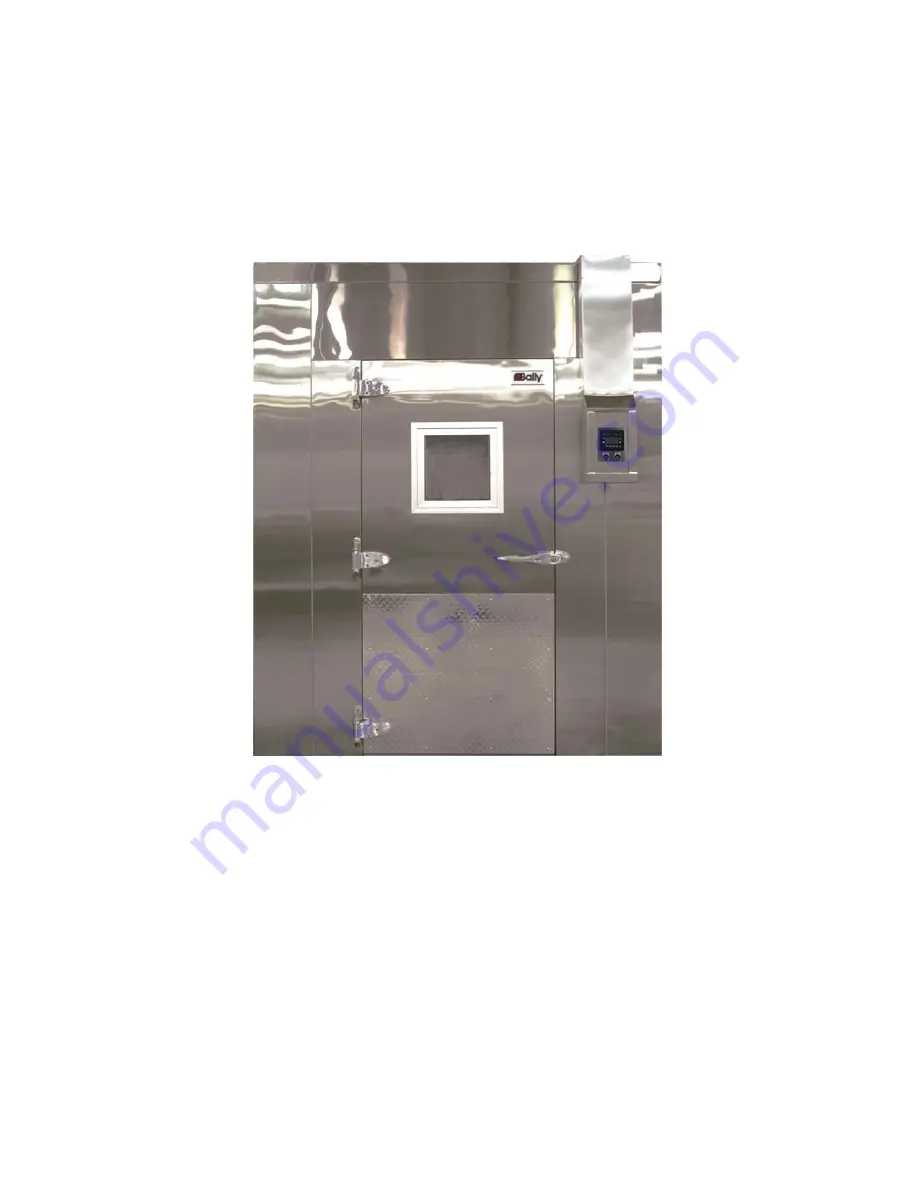
Bally Northwind Blast Chiller 

Models: 500 and1000 


Introduction 


Before turning the controller on, take the time to ensure that all wire connections are secure and 
correctly matched according to the color code set for them.   


Also, inspect all of the external wiring, making sure that all the wiring is correct according to the wiring 
specifications included. 


Now that your Bally Northwind Blast Chiller has been completely inspected, installed, and wired you 
are now ready for operation.   


WARNING: DO NOT OPERATE THE NORTHWIND CONTROLLER WHEN THE CONTROL COVER HAS BEEN 
REMOVED (electrical hazard). 

Summary of Contents for 500

Page 1: ...1 Installation and Operation Manual Northwind Blast Chiller Models 500 and 1000 1 800 24 BALLY Bally Refrigerated Boxes Inc www ballyrefboxes com IM 359 11 2011 Bally Refrigerated Boxes Inc...

Page 2: ...nd parts list and the illustrated plan so that you can complete the installation in a reasonable time without any problems There is also a precise wiring diagram included for any complication and step...

Page 3: ...tep 5 Secure all Panel Sections 8 Step 6 Installation of the Controller 8 Step 7 Installation of Coil Fan Assemblies 9 Step 8 Cable Connections 12 Steps 9 11 Final Assembly 12 Operation Introduction 1...

Page 4: ...4 Note 012993 s are sometimes left out see Chapter 6 3...

Page 5: ...0 Parts List 1 23 Panels 3 2 34 Panel 1 3 Corners 4 4 Ceiling Panels 2 5 36 x 78 Door with electrical junction box complete with twist lock plug wiring 1 6 Control Panel with complete twist lock plug...

Page 6: ...ter to form an interior rectangle which locates the interior blast chiller dimensions 2 Panel Preparation 2 1 Remove all protective paper from panels Leave all special labels on the skins 2 2 During t...

Page 7: ...nt crews have installed boxes upside down Panel assembly sequence of a Northwind 500 The Coil Frame Assembly is installed in the box before the door is added since the coil is taller than the opening...

Page 8: ...back wall Do not fully lock 4 4 Caulk the groove or tongue of the rear ceiling panel and the rest of the wall tongue area 4 5 Bring up the front ceiling panel and lock it to the back ceiling panel fu...

Page 9: ...slot in the front of the box Then push the rectangular collar of the control assembly into the slot until the base of the controller is against the face of the blast chiller Back out the three screws...

Page 10: ...he coil frame into the appropriate side 3 Center the frame within 1 16 between the two walls 4 Install screws into the rear top back brace This will force the frame against the wall permanently 5 Rein...

Page 11: ...lace the Top Fan Trim Piece between the same front cover and the frame 7 4 Installing the Condensate Drain 1 A tube must be installed to drain condensate from each coil assembly 2 Find the pan which i...

Page 12: ...ll on a NW1000 and rear walls You will find screw holes in the walls from our initial assembly Use these first Plenum Installation The plenum is installed with the electrical plug toward the coil fram...

Page 13: ...s done in good practice according to local code Coils arrive with a holding pressure of 60 psi nitrogen 11 Setting the Ceiling Plenum The ceiling plenum can now be set in place plugged in and mounted...

Page 14: ...cording to the color code set for them Also inspect all of the external wiring making sure that all the wiring is correct according to the wiring specifications included Now that your Bally Northwind...

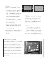
Page 15: ...allow you to monitor two other food locations The auxiliary probes are not necessary for proper functioning of the blast chiller 3 Operating the Blast Chiller 3 1 Automatic The normal or default proce...

Page 16: ...nown to occur Refrigeration Status This is an on off indicator There is sometimes an explanation for a certain refrigeration state for instance if you start the auto mode then open and close the door...

Page 17: ...heaters in the coils will turn on and heat the coil They will stay on even if the door is opened The Defrost cycle ends one of two ways either by a 20 minute timer ending or by the Defrost Termination...

Page 18: ...e time for the manual cycle to run Follow the instructions to adjust the time Any time changes take effect immediately Refrigeration Status This is screen is the same as Auto Fault Page This is screen...

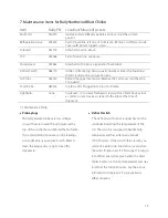
Page 19: ...or is at room temperature and stay in defrost the full 20 minutes See the above information to replace it if you experience either situation Item Bally PN Location Means of Access Fan Motor 016915 Ins...

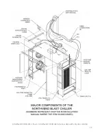
Page 20: ...20 A Northwind 500 Model is shown A Northwind 1000 Model is twice as deep with only one controller...

Reviews: