background image

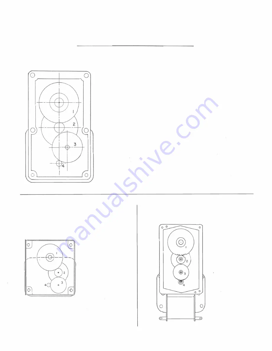
M OTO R  PARTS  G U I D E  

GEAR 

S H A F T   A S S E M BLY. 

2  GEAR. 

3  G E A R .  

CODE 

G E AR  ROTOR 

S H A FT  A S S EMBLY. 

5  S TATOR 

COIL  A S S E MBLY. 

M otor 

( E  

-

1 1 9

-

359

Bearing 

Bracket  Assembly  - - -- - -- Z B B  -7553 -20 

G e a r   Case  Ass 'y.  ( M in us  Stator 

Coil )  - - Z E G B - 4020 - 1 

I. 

Output  Gear 

S h a f t   As s ' y .   - - - - - Z E G S  - 4020 - 1  

2 G ear  - - -- - - -- - - - -- - G - 6 7 1 2 - 32 

3. 

G ear - - -- - - - - - - - - - G L - 6 3 12 - 2 1  

Gear- Rotor 

Shaft  Ass 'y.  - - - - - - Z RS - 403 8 -

'

52

-

1  R.H. 

5  St ator 

Coi l   A ss'y.  - - - - - - -- Z S - 40 1 8 - 26 109 

Mise  Parts 

Fa n  - - - - - - - - - - - P - 1 0 36 - 1  

Oi l   Pad  Retain i n g   Pl ate - - - - - - A - 1 4 1 7  

Oi l   Pa d - -- -- -- -- -- -- - - P - 40 1 0 
Washer , Boltom ( for  ZEGS- 4020 

-I ) 

- -

-

W - 2060 - 2  

Spacer  (fo r   Z E G S - 4 020 - 1 ) - - - - B - 1 8 B 7  
Was her ,  To p  ( for  ZEGS - 4020 - 1 ) - - W - 2044 

S pacer  ( for  G - 67 1 2 - 3 2 )  - -- - - V - 1 30 9 - 3 

Washers ,   Two  ( fo r   G - 67 1 2 -32 ) - - - W- 2078 

Spacer  ( fo r   G L -631 2 - 2 1  ) 

� 

--

-- -- V - 1 309 - 1  

Washers,  Two  ( for  G L- 6 3 1 2 - 2 1   - -- W - 2 0 7 7  

SHUTTER 

MOTOR 

( E - 1 1 9 - 3 38 ) 

ZGS - I 7 2 5 - 1 5  

G - 58 1 8 - 1  

M Y STIC 

LINE 

"A"  M OTOR 

3  C - 4 1 09 - 1  

(  E  - 1 1 9  - 3 5 2  ) 

ZRST- 1 7 1 5 - 3 0 - /  

HGS - 1 7 26 - 1  

Z S -1 7 0 8 - 2 5 1 9  

G - 58 1 8 -1 

G - 4 1 0 9 - 1 

4  Z R S T - 1 4 1 5 - 32 - 8  

Z S - 1704 - 2 5 2 1  

M Y S T I C  

L I N E S   " B "  

" c "  

MOTOR 

BALL 

LIFTER 

MOTOR 

( E - 1 I 9 - 35 3   ) 

( E  - 1 1 9 - 33 9 )  

HGS - 1 744 - 1  

Z G S - 1745 - 12 

G - 531 8 - 1 

G - 53 1 8 - 1  

3  G - 4 1 1 4 - 1  

3  G - 4 1 14 

- I  

Z R ST - 1 4 1 5  - j 2 - 9  

Z R ST - /7/5 -30 - 1  

Z S - 1 70 3 - 2 5 2 2  

5  Z S - 1 7 0 8 - 2 5 1 9 

49 

Summary of Contents for Super-7

Page 1: ......

Page 2: ...he Wiring Diagram Wire Code Infor mation This Special operating instruction edition for Super 7 is meant to be used in conjunction with the recently released Bingo Games Parts Catalog Manual 1000 Seri...

Page 3: ...2 BACK CAB I N ET U N IT LAYOUT PAG E I N DEX 18 17 _ i r ti 16 15 14 2 3 4 13 8 5 6 7 9 10 11 12 ALWAYS GIVE MODEL AND PART NO WHEN ORDERING SERVICE PARTS...

Page 4: ...t 8 E 133 10A Fuse 10 Amp 5 Req d Motor Unit Discs 9 Relays 44 13 E 126A Cord Set 3 AS 827 237 ND Mystic Lines Feature Unit 15 14 AS 798 107 ND Control Unit Assembly 11 14 Search Disc 10 4 AS 797 111...

Page 5: ...pJf BACK DOOR U N IT LAVOUT PAGE I N D EX 6 ALWAYS GIVE MOOEL ANOPART NO WHEN ORDERING SERVICEPARTS 4...

Page 6: ...Search Relay 35 1 Red Button 39 2 Red Letter 2 39 3 3 Search Relay 35 3 Red Letter 1 39 4 Up Down Play 4 2 Search Relay 35 Diamond Play 38 5 Steering 38 5 1 Search Relay 35 6 Cam 7 38 7 Z 38 6 AS 102...

Page 7: ...j1af i1 CONTROL B OARD LAYO UT PAG E I N D EX 13 5 ALWAYS GIVE MODEL AND PART NO WHEN ORDERING SERVICE PARTS 6...

Page 8: ...ay Counter Unit Diamond Relay Bank 5 Note The following Relays are component parts of Index No 7 E 300 542A Reflex Relay Diamond Win Relay Missed Relay 2nd Ball Relay 1st Ball Relay Diamond Relay Bank...

Page 9: ...8 Y5 R5 9 10 85 G5 II 12 85 R5 13 14 B5 Y5 15 16 85 Y5 17 18 G2 G3 19 2 0 GI G3 21 22 GI G2 23 24 GI G2 2 5 26 82 83 2 7 28 81 B3 29 30 BI 82 3 1 32 81 82 33 3 4 R2 R3 3 5 36 RI R3 3 7 3 8 I R2 3 9 4...

Page 10: ...SC WIREDl W I 063 2 WIPER ASS Y A 1 371 96 o MOTOR HOMING ON DIAG S 14 0880000000 COMPLETE UNIT MOTOR A LINE MOT OR S 8 c LINES AS ISW II E 119 352 TO CARD LITES 8 SEARCH DISC FROM HOLE SWITCHES ON DI...

Page 11: ...8 Os 80 O 00 000 t00 OO Oo 0 00 G eOO O ___ 00 0 eG 080 08 f2i 000840 LT 0 08 00 00 v lG 0 0 00 0 0 RELAY 0 4 5 0 08S0668cCY 1516 0000 8 80 C008 0 J oGre 0 00 00000000 0 u 5 8 0 00000 00 Oee 0 0 oeO O...

Page 12: ...lay cams Index coli is energized CORRECT ADJUSTMENT CONTROL UNIT SWITCHES 12A 12El 12C 8 12E NOTICE IMPORT ANT PART OF IL LUS T R ATI ON I S TO SH O W THAT SWfTCHI2ECLOSES FIRST AND OPENS LAST IF AN A...

Page 13: ...ange 5A N o A 19 23 7 Blue Yellow Completes circuit for extra ball unit single steps 78 4 Orange Black 5B N o B 20 91 6 Gray Red Completes pull in circuit to anti cheat relay 85 4 Black White Complete...

Page 14: ...N o B 32 90 1 Gray replay register unit steo up 27 17 Blue Orange Completes 4 star 600 winner circuit to step 4 star replay counter unit at a 1 to 12 ratio with replay register unit lOB N o B 29 23 17...

Page 15: ...E 40 43 10 Green Yellow Ooens lock in circuit to diamond reflex rela 85 4 Black White E N o B 25 10 9 Red Completes circuit for twin number feature unit single steps 57 4 White Orange Opens lock in c...

Page 16: ...Note 1 This is wiring side of Disc 000 55 0 0 25 0 14 _ e e o 0 ____ D O u ______ OC 50 23 ____ 80 3 I Oo s 0 Go E I I s 3 0 DIRECTION OF ROTATI lN 15 CD 1 1 I2 S 2 115 151 C 8 145 14 0 43 12 0 4H2 0...

Page 17: ...o o o G C0 o COMPLETE UNIT AS 827 236 RArcHET a SWIFT C IO lO 7 40 RESET COIL C 26 1 I00 RESET PLUNGER S 496 IOI STE P UP COIL B 2 5 925 STEP UP PLUNGER S 4 96 100 STE P UP ARM ASS Y A 1765 4 WIPER F...

Page 18: ...LUNGER AS 797 1 1 1 C 28 1 I 00 B 25 925 S 496 1 1 6 A 1 765 8 C I O O 5 496 101 Con rol Uni Mul iplier Cam Switches That Advance Green Red Yel low And Blue Re play Coun er U n i s Dur ing 3 4 5 IN A...

Page 19: ...O O DIS C wired W I064 1 WIPER ASS Y A S I 0 46 634 30 WIPER ROTATION COMPLETE U N I T AS 827 425 RATCHET a S HAFT C 1060 STEP U P C O I L B 25 92 5 STEP UP PLUNGE R S 496 16 2 STEP UP AR M ASS r A 17...

Page 20: ...ATURE GREEN MULT I P L E FEAT URE 57 1 5 1 0 0 Wiper 9FMdc C0 8 0 0 8 8 0 0 0 0 0 0 0 0 0 0 0 0 0 0 0 0 0 0 NOTE This is wiring side of Disc o 30 DIRECTION OF ROTATION 0 0 0 0 0 0 0 0 0 0 1 0 0 0 0 CO...

Page 21: ...TEP A DVANCE O N DIAG B 19 T HRU WIPER BAl L DE T E CTOR RELAY A BALL LIFTER tojOTOR FOR EXTRA BALLS ON DJAG G I I THRU WIPERS EXTRA BALL UNIT SINGLE STEP ADVANCE ON DIAG B 19 COMPLETE UN I T AS I I 4...

Page 22: ...n 83 15 18 14 31 lB 43 5 81 4 43 38 7 36 6 81 2 40 4 50 8 56 12 57 5 74 8 61 19 43 7 5 3 12 25 2 71 5 30 1 8 w G 0 0 0 0 0 B B 0 G G B 0 0 S 8 27 104 G 7 4 9 8 7 1 4 8 65 6 8 2 1 7 CD 2 IO 0 6 IO 0 31...

Page 23: ...D BE USED I I I I I I I I I I I I I I I I I I i i WHEN NECESSARY 1 1 I I MIXER 4 M I X E R 3 MIXER 2 I I I I I I I I I MOTOR I E 1 1 9 359 e l f Jf 1 MIXER II 5 DISC W 1 076 6 I MIXER II 5 WIPER ASSY...

Page 24: ...a r game f e a t u r e un i t s a nd e neg i ze feature t r ip re l s Comp l e t e s S upe r 7 d i amond feature w i n c i rc u i t to co l lect a double shoot r ed shoot y e l low shoot red l i tes...

Page 25: ...1765 14 DIRECTION OF ROTATION THRU WIPER CD I 8 2 EXTRA STEP R E L AYS ON OIAG 8 64 0 8 8 FEED o 0 e e THAIJ WIPERS 8 MIXER 4 RELAY ON DIAG C 16 THRU WIPER Y E L LOW SCORE UNIT ADVANCE MULTIPLE SCORE...

Page 26: ...AS 1022 I D4 RATCHET a SHAFT C 1060 10 47 DI ECTfON OF ROTAT I ON RESET COIL C 2 8 IIDO RESET PLUNGER S 496 10 I STEP UP COl L c 28 l iDO STEP UP PLUNGER S 496 162 STE P U P ARM ASS Y A 1 7 6 5 14 25...

Page 27: ...e d l W 055 2 WIPER ASS Y AS 10 4 6 580 CO PLETE UNIT AS 10 2 2 105 RATCHET B SHAFT IOGO 10 47 R E S E T COIL 28 1 1 00 RESET PLUNGER S 496 1 0 1 STEP UP COIL 8 2 5 925 STE P UP PLUNGER 5 49 6 162 STE...

Page 28: ...18 11 8 10 ffi 12 17 8 38 14 10 iTHRU WIPERS TWIN NO 0 58 6 ARROW AND FEATURE LITES ON DIAG G 28 0 0 THRU W I PERS 0 STEERING RELAY 815 ON D I AG F 27 8 0 0 iTHRU WIPERS TWIN NO ARRCW AND FEATURE L I...

Page 29: ...NS NOW LITE BEFORE 4th BALL ON DIAG H 4 T H R U WIPER 0 TIMER UNIT ADVANCE 0 THRU 4 1h STEPS ON DIM F 7 WIPER AND FEED THRU WIPER SHUTTER MOTOR CLOSE SHUTTER ON DIAG F a 8 6 THRU WIPERS BEFORE 4 111 B...

Page 30: ...RE ADVA NCE ON DIAG D 4 2 _ _ _ J THRU W I P ER D I A M OND SCORE ADVANCE ON DIAG C 41 2 45 131 16 2 1 6 1 71 17 THRU WIPER D I A MO N D SCORE ADVA N C E 9 16 ON DlA G B Ii e e e 0 8 0 o o o o o NOTE...

Page 31: ...1 765 8 THRU WIPER 0 3 4 5 BALL OIA OND fEATURE SHOOT fOR REO Y ELLOW R EO HOLE LITES ON OIAG H 32 THRU WIPER DIAMOND FEATURE WINNER SCORING SOURCE ON DIAG F 44 THRU WIPER MULTIPLE WIN RELAY 1 DURING...

Page 32: ...DURING 2 3 4 5 8ALL SUPER 7 DI AMOND F E ATURE WINNERS DURING 4 B 5 BALL WINNERS SWITCHES DOUBLE 8 QUADRUPLE THEIR REGULAR MULTIPLIER RATIO THRU MULTIPLE U N I T DISC lOA 72 144 288 576 X I 2 0j I I...

Page 33: ...Q _8 1 2 6 10 Q 9 9 2 2 8 C3 4 I t Till D1 l l C YB 0 1m l 0 1 11 1 0 1 R 1 o C I 2 M F D 50 V D I I N9 1 4 A R2 8 tt l II I R R l l J rm Q 0 10 RB R E S I S T O RS PUL G1 R I 4nl 1 4 W 1 0 R2 I K 1 4...

Page 34: ...No C l E 586 8 Electro lytic 2 MFD 5 0 V 2 1 R S E I04 73b D 2 E 5 8 7 6 Diode EM5 0 2 3 3 R 6 E I08 168b Q l E 58 5 2a Tran s istor MP S 6 S 6 6 6 R 7 E IOS 167b Q 2 E 5 8 5 1 1a Tran s i stor D40C...

Page 35: ...ng un it motors Directs s ingle Play reset c ircuit or reset circu t to replay reg ister unit mUltiple Cancel Opens start relay circuit Extra switch not used in circui t Opens key plays circuit to ste...

Page 36: ...1 Gray Energized thru yellow red blue green score winner cir 2 relay coil A 34 70 Orange cuits and Super 7 diamond feature score winner circuits 75 6 Orange White 1 N o C 31 78 9 Orange Black Complete...

Page 37: ...lue Yellow relay co i l A 16 70 Orange Energized during play cycles thru feature control c ircuit 18 7 Red Black 1 N o A 14 2 3 4 B lue Ye llow Com pletes lock in c i rcuit to this re lay 36 19 Yello...

Page 38: ...4 N c H 7 31 16 YellOW Red lites Scores lock 93 14 Gray Yellow relay coil A 38 31 15 Yellow Red Energized thru play scores relay circuit 58 11 White Black Completes spotting disc control circuit for y...

Page 39: ...A 27 70 Orange Enerqized thru twin number feature control circuit 98 1C s iiH k 18 1 Ll S P D T H 28 10 1 Red Directs twin number feature lite circuits 8 10 or 12 17 63 g Brown Yellow 78 1 Orange Bla...

Page 40: ...reen Ope n s r e g u l a r ye l low score u n i t step up c ircu i t Gray Wh i te Red Green Red Ye l low Ope n s regular b lue green score unit s t ep up c i rc u i t Wh i t e Brown Energized t h r u...

Page 41: ...e White L5 S P D T C SJ 75 8 Orange White extra steps 81 9 Black Red Opens control circuit for red score unit single and extra Rl N c C U 5A 10 White Black steps 13 11 Red Yellow 90 19 ed White aeg Er...

Page 42: ...f o r ye l low red b lue a n d green unit steps and ye l low red blue mu l t iple features SWITCH LOCAT I O N IWIRE No l WIRE COLORS Ye l low multiple 1 13S l7i Ye l lo B lack re1av coil A 58 71 13 Or...

Page 43: ...letes a circuit to ball lifter motor Opens spotting disc circuit to flash other game feature lites SWITCH LOCATION ON DIAGRAM WIRE No WIRE COLORS R2 N c 83 9 E 22 150 5 B lack Yellow White R3 S P D T...

Page 44: ...B I N ET RELA Y BANK 3 LOCATION WIRE WIRE COLORS FUNCTION OF SWITCHES SWITCH O RA No B a l l l i f t 5 1 1 White Red Energ ized by c ircuits thru diamond feature components a lso by bal return hole ci...

Page 45: ...erGized thru ball runway switch c i cuit when eQch ball Yrl T Y to shooter de energ zed when each ball enters I e a w t t g e i I rIo u i Gl r s wrgn v e search Directs 5 ball d amond w nner search c...

Page 46: ...1 4 Yel low Red 5B N o F 37 90 9 Gray I n series with l ifter start relay lock in circuit 8 5 1 B lack White In serie s with feature unit advance an d feature trip re lay SC N o D 2 2 5 0 5 Wh ite c...

Page 47: ...9 Blue Yellow 48 1 9 Green Black Completes yel low holes diamond feature mi s s or hit 4 N o F 55 27 12 B lue Orange c ircuits on 3 r d 4th 5th balls 4 step 25 20 B lue Wh ite Energized by 4 pulse mo...

Page 48: ...it 85 4 Black White R4 N c G 5 2 8 3 7 Black Yel low Opens circuit to all diamond feature components 7 win 91 8 Gray Red Energized thru diamond feature disc hit circuit on 2nd relay coil A 5 6 7 0 Ora...

Page 49: ...ature unit step up Gray Black circuit or miss relay circuit thru feature unit disc Red White Red Yellow Completes circuit to 2nd ball relay Red Black Completes 1st and 2nd ball diamond feature unit st...

Page 50: ...om for ZEGS 4020 I W 2060 2 Spacer fo r ZEGS 4020 1 B 1 8B7 Washer To p for ZEGS 4020 1 W 2044 S pacer for G 67 1 2 3 2 V 1 30 9 3 0 _ _ _ _ _ _ 0 Washers Two for G 67 1 2 32 W 2078 Spacer fo r G L 63...

Page 51: ...ng Only A 1 27 2 17 Button A A 1 2 7 2 1B Button B A 1 2 7 2 1 9 Button C A 1 2 7 2 2 9 Button R Coin Entry P late Panel Assembly AS l 3 1 s AS 493 2 R 1l5 4 C 1l9 23 C 1 l 9 2 1 R l 3 s R 243 R 24 3...

Reviews: