Installation manual phase inverter (16/32A)
(08.2016)
13 / 28
5. Strip the cable to the required length (16A designs: 60 mm; 32 A designs: 70 mm).
6. Remove the insulation from the individual conductors (16 A designs: 7 mm; 32 A designs:
12 mm).
7. For better, permanent contact, provide the individual conductors with suitable conductor end
sleeves.
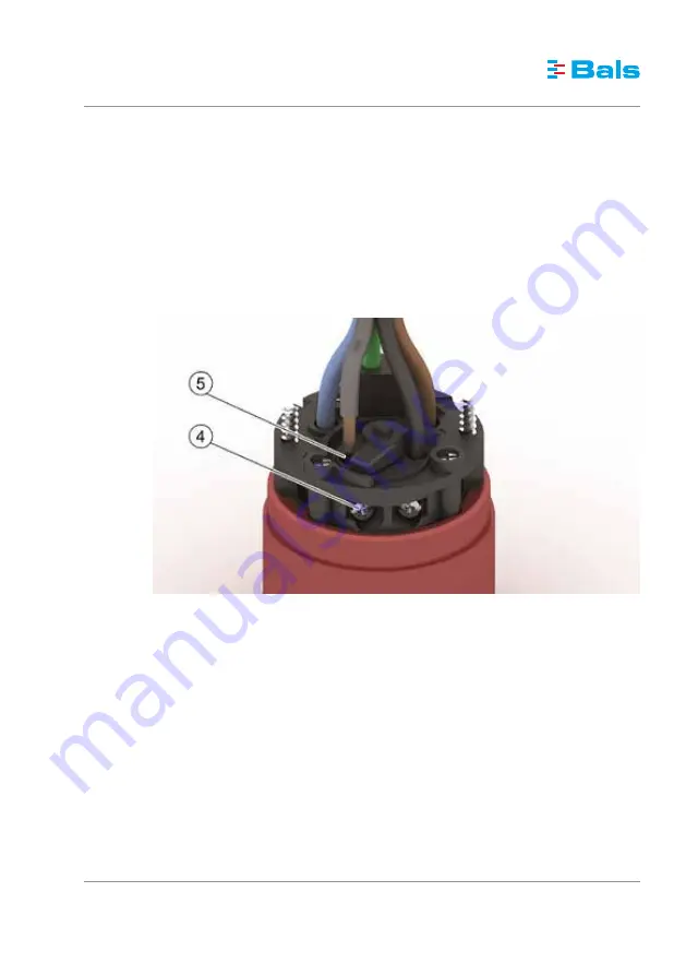
8. The terminals are open at the time of delivery. Guide the individual conductors into the open-
ing (5) and tighten the screws (4) with a torque of at least 0.8 Nm. Take care to see that only
the individual conductor (without insulation) is clamped. Pay attention to the marking of the
terminals and ensure that the assignment of the individual conductors to the terminals is cor-
rect.
9. Connect the housing and the insert with the screws foreseen for this purpose.
10. Next, tighten the cable gland (3). The tightening torque must be between 4 Nm and 7 Nm for
the 16A designs and between 5 Nm and 9 Nm for the 32A designs. Please refer to the em-
bossing on the cable gland for the exact value of the respective design. Secure the cable gland
using the screw placed on the side for this purpose (6, depending on the design).


