9
32.
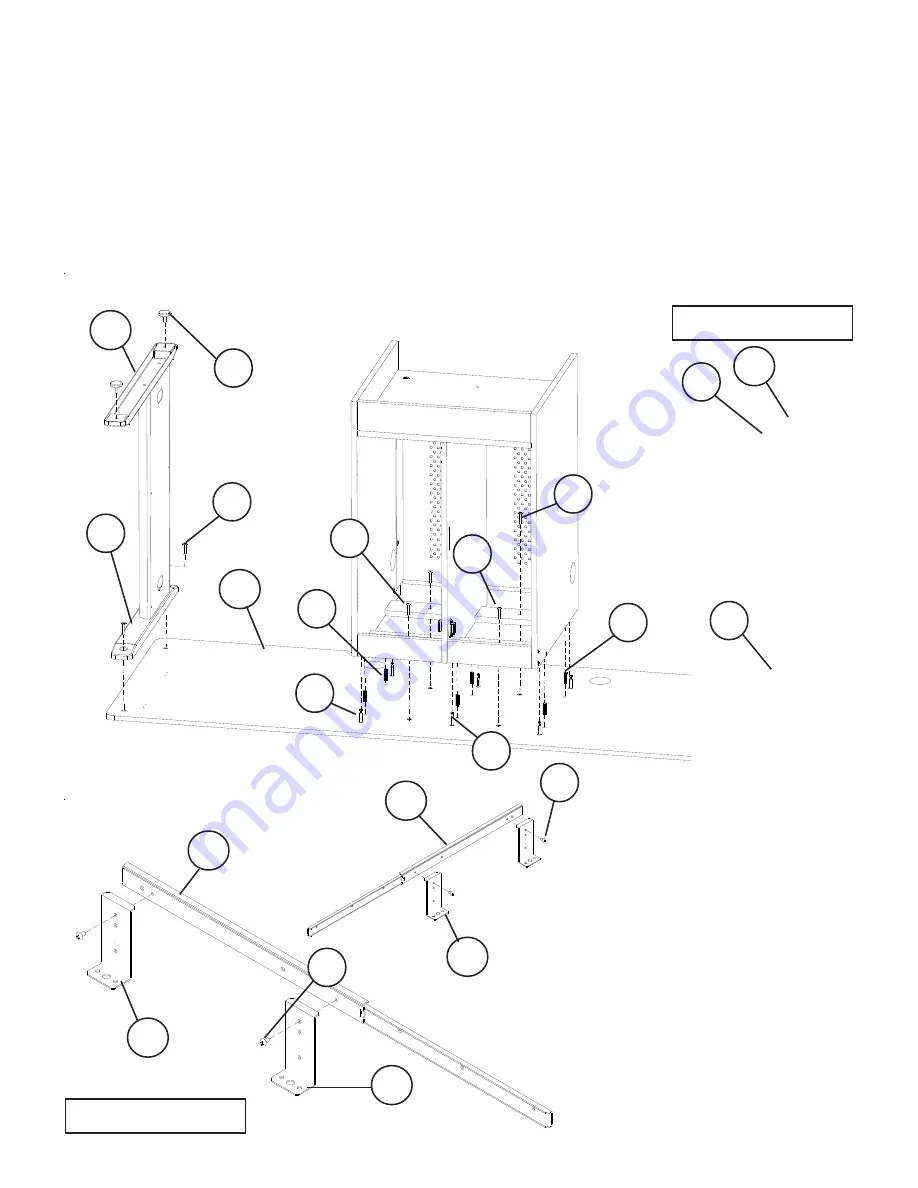
Illustration # 10
31.
33.
35.
Place the Table Top (P-13) with the Predrilled holes facing up and install 6 each Cam Posts (D)
in the 6 threaded insert nuts (Pre-installed) as shown in illustration # 10.
Install 6 Wood Dowels (E) into the 6 holes as shown in illustration # 10.
Slide Wood CPU Assembly over the Wood Dowels (E) and the Camposts (D) in the Table Top
(P-13) as shown in illustration #10. Turn the Cam Locks (C) 1/4 turn until they lock.
Secure Wood CPU Assembly to the Table Top (P-13) using 4 screws (A).
Attach 2 Upper Leg Mounts (P-9) to the Top Panel (P-13) using 4 each Socket Screws (A)
as
shown in illustrations # 10.
Tighten Screws using Allen Wrench (V).
P-9
A
E
A3
D
P-15
P-15
P-16
A3
P-16
Attach 2 Keyboard Brackets
(P-16) to 1 Keyboard Slide
(P-15) using 2 Screws (A3)
as
shown in illustrations # 11.
Attach 2 Keyboard Brackets
(P-16) to 1 Keyboard Slide (P-
15) using 2 Screws (A3).
Note: The 2 Slides will have
Brackets are on the oppo-
site sides.
Illustration # 11
34.
36.
A
E
D
F
P-10
A
P-16
Install 4 Leveling Glide (F) in
the bottom of the Lower Leg
Mounts (P-10) as shown in
illustration #10.
P-13
37.
38.
F
A
A
P-10


