Technical staff manual
10.PUTTING THE BOILER INTO OPERATION (INITIAL RUN)
If the boiler was at sub-zero temperature during its transportation and storage, it must be held at positive
temperature (not less than 5
o
C) during 2…3 hours before the initial run.
The requirements to the heat carrier of the heating system are represented in p. 7.2 (page 13).
10.1.
Filling the CHwith water and prelaunching check
1)
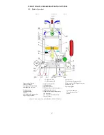
Release the air output valve 8 (see p. 13.1, page 27) (located on the pump 7), turning off its cap for
1,5…2 turns;
2)
Open step-by-step the cold water inlet tap on the DHW line by the inlet into the boiler, CHfeed tap
24 and stop valves on the direct and reverse lines of the CH(if they are installed);
3)
Close the boiler’s feed tap 24, when the pressure in the CHreaches 1-2 bar, (according to the
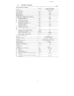
pressure gauge readings) in accordance with the technical characteristics table (see p. 2.2, page 5).
The recommended pressure is 1,5 bar. If the pressure is lower than 1 bar it is prohibited to put the
boiler into operation;
4)
Switch the boiler on, not opening the gas tap, so that the pump completely removes the air from the
heating system. Herewith the pressure may reduce lower than 1 bar and the boiler will show the
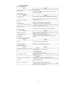
error 04 (insufficient heat carrier pressure in the heating circuit). In order to remove the error you
need to press the button K6 (RESET) (see p.3.1, page 8).
Repeat the actions according to the points 1-4 until the pressure in the CHstabilizes at the level of
1,5 bar, that will indicate that the air is fully removed. The installation of additional air output valves
is recommended at the upper points of the heating system for more fast and complete air removal.
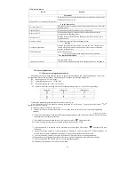
Before a test ignition of the boiler it is necessary to check whether:
1)
The boiler installation was effectuated in accordance with the requirements indicated in section 8
(page 14) “Boiler installation”;
2)
The heat carrier pressure in the heating system is 1-2 bar ( the recommended pressure is 1,5 bar).
If the pressure is higher than 2 bar – the drain valve 14 must be opened (see p. 13.1, page 27),
reducing the pressure for 1,5 bar. If the pressure is lower than 1 bar – the CHfeed tap 18 must be
opened and it must be closed when the pressure reaches the level of from 1 till 1, 5 bar;
3)
The air inlet and smoke exhauster pipes are installed and comply with the requirements of
section 9, page 17;
4)
The power line’s voltage and frequency correspond with the levels indicated in the table 1(see p.
2.2, page 5);
5)
The type of consumed gas must correspond with the type of gas indicated in the sections 20 and
21 (page 48) of this manual and the type of gas indicated on the table on the boiler;
6)
There is no gas leakage ;
7)
The air outlet valve is opened;
8)
The stop valves on the direct and reverse lines of the CHare opened;
9)
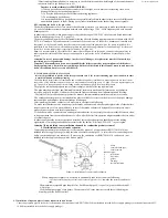
The pump is not blocked. To find it out you may screw off the pump’s cover plug with a screw
driver and turn the pump shaft back and forth several times (see Scheme 12), herewith the boiler
must be disconnected from the power line (take the connector out of the AC outlet).
Summary of Contents for NEVALUX-8230
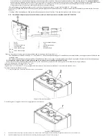
Page 35: ...Assembly is performed in reverse order Scheme 23 Heat exchanger dismantling...
Page 41: ...48...
Page 47: ...Ignition and ionization plugs in the assembly pos 67...
Page 54: ......
Page 55: ......


