Technical staff manual
ATTENTION! In case of long-term idleness of the boiler in winter time in case of using
water as a heat carrier or in case of pipeline freezing danger appearance it is necessary
to drain the heat carrier from the boiler and the heating system.
11. BOILER’S POWER REGULATION
The boiler’s power regulation boils down to setting up the gas supply regulator.
ATTENTION! Setting up the gas supply regulator must be effectuated only with a non-magnetic screw-
driver.
ATTENTION! Setting up the gas supply regulator or rendering the boiler from one type of gas to another
must be effectuated only by specialized service organizations.
11. Preparing for operation
1)
Switch the boiler off (see p. 10.4 , page 24) and throw open the
lid of the front panel;
2)
Screw out 6 self-threading screws of the front panel fixation;
3)
Throw open the front panel together with the lid;
4)
Remove the plastic cap from the regulation screws В and Г
(see Scheme. 13).
11.2.
Checking gas pressure by the regulator’s
inlet
1)
Screw off the cover plug from the control point Б and connect
the pressure gauge;
2)
Turn the boiler on and render it to the heating mode (see p.
3.2.4, page 10);
3)
Detect the rated power, switching on the gas analysis function
(see p. 13.3.2, page 31);
4)
Keep the boiler in the heating mode for 1 minute;
5)
Check gas pressure in the control point Б. It must correspond:
—
1,3 kPa - 2,0 kPa (130 - 200 mm w.g.) for natural gas;
—
2,9 kPa (300 mm w.g.) for liquefied gas.
Otherwise it is necessary to switch the boiler off and address to gas facilities emergency service, or to replace
the gas cylinder (for liquefied gas);
6)
To render the boiler to standby mode,
consequently pressing the button K5 (see p. 3.2.4, page 10);
7)
To disconnect the pressure gauge and screw up the cover plug in the control point Б up to the stop.
11.3. Regulating rated pressure
1)
Screw off the cover plug in the control point А and connect the pressure gauge to it;
2)
Switch the boiler on and render it to the heating mode (see p. 3.2.4, стр. 10);
3)
Detect the rated power, switching on the gas analysis function (see p. 13.3.2, page 31);
4)
Keep the boiler in the heating mode for 1 minute;
5)
Check gas pressure in the control point А. It must correspond:
—
1,1 kPa (113 mm w.g.) for natural gas and 2,8 kPa (284 mm w.g.) for liquefied gas;
Otherwise it is necessary to set required pressure by turning the regulation screw Г, keeping at the same time
the inner screw В from turning.
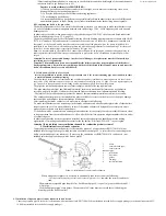
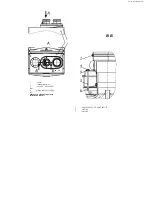
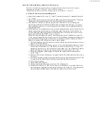
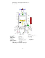
Scheme 13. Gas supply regulator
Summary of Contents for NEVALUX-8230
Page 35: ...Assembly is performed in reverse order Scheme 23 Heat exchanger dismantling...
Page 41: ...48...
Page 47: ...Ignition and ionization plugs in the assembly pos 67...
Page 54: ......
Page 55: ......

