6
Operation and Maintenance Schedule
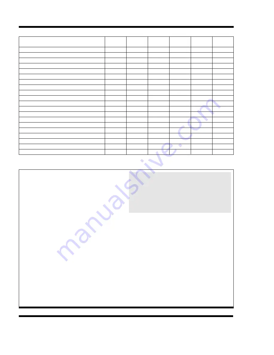
TABLE 1. Recommended Maintenance Services for Series V and Low Profile Series V Equipment.
TYPE SERVICE
Start-Up
Monthly
Every Six
Months
Shutdown
Annually
Ref. Page
Inspect General Condition of Unit
Clean Debris from Unit
Clean and Flush Basin
Clean Basin Strainer
Check and Adjust Basin Water Level
Inspect Heat Transfer Section
Inspect Spray Nozzles
Check and Adjust Fan Belt Tension
Check and Adjust Bleed Rate
Check Operation of Make-up Valve
Check Unit for Unusual Noise or Vibration
Check Fan Bearing Locking Collars
Check Motor Voltage and Current
Lubricate Fan Shaft Bearings
Lubricate Fan Motor Bearings
Lubricate Motor Base Adjusting Screw
Check Fan for Rotation Without Obstruction
Check Fan and Pump Motor for Proper Rotation
Drain Basin and Piping
Inspect Protective Finish
X
X
X
X
X
X
X
X
X
X
X
X
X
X
X
X
X
X
X
X
X
X
X
X
X
X
X
X
X
X
X
X
X
X
X
X
X
X
X
X
7
7
7
7
8
11
11
11
14
8
7
10
7
9
10
10
7
7
7
12
WARNING:
Before performing any maintenance or inspection, make certain that all power has been
disconnected and locked in the off position.
WARRANTIES—Please refer to the Limitation of Warranties applicable to and in effect at the time of sale/purchase of these products.
FREEZE PROTECTION—These products must be protected by mechanical and operational methods against damage and/or reduced
effectiveness due to possible freeze-up. Please refer to the Cold Weather Operation guidelines (page 12) or contact the local B.A.C.
Representative for recommended protection alternatives.
SAFETY: The operation, maintenance, repair of this
equipment must be undertaken only by qualified per-
sonnel. All qualified personnel should be thoroughly
familiar with the equipment, the associated system and
controls, and the procedures set forth in this manual.
Proper care, procedures, and tools must be used in
handling, lifting, installing, operating, maintaining and
repairing this equipment to prevent personal injury
and/or property damage.
Lockout Warning: For the protection of authorized ser-
vice and maintenance personnel, each fan and pump
motor associated with this equipment must be installed
with a lockable disconnect switch located within sight of
the cooling tower. No service work should be per-
formed on or near the fans, motors, and drives or inside
the unit without first ensuring the fan and pump motors
have been disconnected and locked out.
Electrical Hazard: All electrical, mechanical, and rotat-
ing machinery constitute a potential hazard, particularly
for those not familiar with its design, construction, and
operation. Accordingly, adequate safeguards (including
the use of protective enclosures where necessary)
should be taken with this equipment both to safeguard
the public (including minors) from injury and to prevent
damage to the equipment, its associated system, and
the premises.
WARNING: PVC eliminators on this product are
not designed to support the weight of a person or
to be used as a storage or work surface for any
equipment or tools. Use of these PVC eliminators
as walking, working or storage surface may result
in injury to personnel or damage to equipment.
Units with PVC eliminators should not be covered
with a clear plastic tarpaulin.
Access: Depending upon site conditions, it also may be
necessary to install bottom air inlet screens, ladders,
safety cages, stairways, access platforms, and handrails
and toeboards for the safety and convenience of autho-
rized service and maintenance personnel.
At no time should this equipment be operated
without all fan screens, access panels, and access
doors in place.
Caution: The recirculating water system may contain
chemicals or biological contaminants, including Legionella,
which could be harmful if inhaled or ingested. Accordingly,
personnel who may be exposed directly to the discharge
airstream and the associated drift, mists generated during
operation of the water distribution system and/or fans, or
mists produced by high pressure water jets or compressed
air, should these be used to clean portions or components
of the recirculating water system, should wear respiratory
protection equipment approved for such use by OSHA
and/or local occupational safety and health authorities.


