n°
000
29
36
96
0
Pa
nn
ell
ino
.tif
f
10 / 26
0006081534_201512
ENGLISH
D E S C R I P T I O N O F T W O - S TA G E
PROGRESSIVE OPERATION
Burners work in progressive/modulating two stage operation, the
gas train provided is composed of an ON/OFF type safety valve
and a proportional adjustment/regulation main valve.
Adjusting the air flow rate is performed using the combined actions
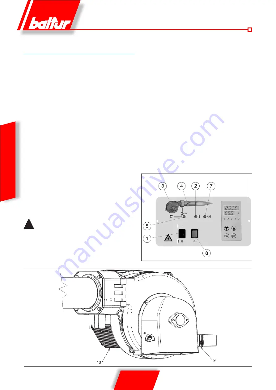
of the air gate activated by the servomotor (9) and the inverter (10)
which drives the rotation speed of the electric motor hence varying
the air flow produced by the fan. The gas flow adjustment is carried
out using the main valve, equipped with a device to proportionally
adjust the air/gas ratio.
The inverter allows the programming of three rotation speeds for
the electric motor:
V1: rotation speed in relation to the minimum power.
Vs: rotation speed in relation to the ignition stage
V2: rotation speed in relation to the maximum power.
To adjust the V1, Vs, V2 speeds consult section: “Instructions for
adjusting the frequency of the inverter output”.
When the main switch (1) is closed, if the thermostats are closed,
the voltage reaches the command and control equipment which
starts the boiler (LED 2 ON).
This turns on the fan motor (LED 3 ON) for preventilation of the
combustion chamber. During the preventilation phase the motor
goes to speed V2.
At the same time, the rotation of the servomotor (9) puts the air
gate into the open position which corresponds to the maximum
power setting.
At the end of the preventilation phase the air gate goes to the ignition
position (for the adjustment of the ignition cam of the servomotor
refer to table 0002933651).
!
The flow rate of gas in the ignition stage should
generally be greater than the minimum flow modulation.
Meanwhile the inverter turns the motor at the Vs speed programmed
for the ignition stage.
If the air ventilation control pressure switch has found that there is
sufficient pressure, the ignition transformer will be activated (LED
4 ON) and, after two seconds the gas valves (LED 5 ON) will be
opened.
The presence of the flame, detected by the control device, permits
continuation and completion of ignition, turning off the ignition
transformer (LED 4 OFF).
Then the servomotor opens the air gate gradually, the inverter
increases the rotation speed of the motor up to V2 and the pneumatic
valve allows an increase in the gas flow up to the maximum set value.
In the event that the control device does not detect the presence
of a flame, the control box activates a “safety shut down” (LED 7
ON) within 3 seconds of the opening of the main valve. In “safety
lock-out” mode the valves are closed again immediately. To release
the equipment from this safety position you have to press button 8
on the synoptic panel.
Summary of Contents for 17490020
Page 2: ......
Page 28: ...26 26 0006081534_201512 ITALIANO...
Page 54: ...26 26 0006081534_201512 ENGLISH...
Page 55: ......


