0002934691
Mod.
A
B
C
TBG 85 PN-V
5
3
3
TBG 85 P-V / PN-V
0002935021
11 / 26
0006081534_201512
ENGLISH
MODULATION OPERATION DESCRIPTION
When the burner is ignited at the minimum setting, if the modulation
probe allows it (adjusted to a temperature or pressure which is
greater than that present in the boiler) the air adjustment servomotor
begins to turn causing a gradual increase in the flow of air and
consequently gas, up to the maximum flow to which the burner is set.
The increase in ventilator air pressure is detected by the proportional
gas valve sensor, which gradually adjusts the gas flow to the air
pressure variation, which is also gradual. The burner remains in
the maximum flow position until the temperature or pressure is high
enough to trip the modulation probe, which reverses the rotation of
the air adjustment servomotor.
Reverse rotation of the servomotor, and consequently a reduction in
gas and air flow, is effected in a series of short steps. By this method,
the modulation system operates to bring the amount of heat supplied
to the boiler in line with the heat that the boiler puts out to service.
The modulation probe fitted to the boiler measures any request
variations and automatically adjusts the fuel
and combustion air supply, by cutting the modulation servomotor
and increasing or reducing rotation.
During operation, the rotation speed V of the fan motor is driven by
the inverter according to the air gate position. The rotation speed
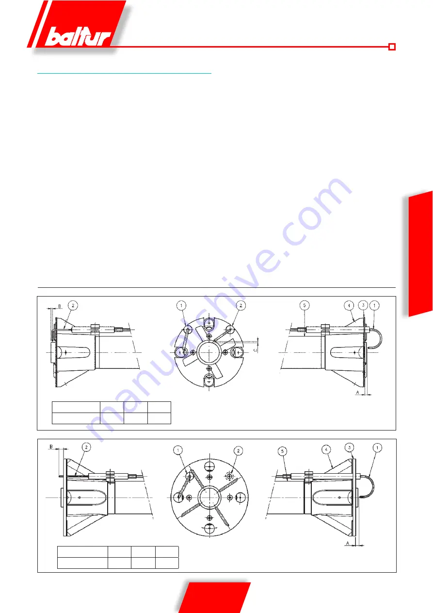
1- Ionisation electrode
2- Ignition electrode
3- Flame disk
4- Mixer
5- Gas outlet pipe
V assumes an intermediate level between V1 (rotation speed
corresponding to the minimum opening) and V2 (rotation speed
corresponding to the maximum opening) and adjusts linearly
according to the rotation angle of the servomotor. If the limit value
(temperature or pressure) at which the stop device is set (thermostat
or pressure switch) is reached even with gas supply at minimum
level, the burner is shut down by the device.
When temperature or pressure drops below the shut-down device
tripping value, the burner is activated once again according to the
program described in the previous section.
Mod.
A
B
C
TBG 80 LX PN-V
5
8
-
TBG 80 LX PN-V
1- Ionisation electrode
2- Ignition electrode
3- Flame disk
4- Mixer
5- Gas outlet pipe
ELECTRODES/IONISATION PROBE ADJUSTMENT DIAGRAM
Summary of Contents for 17490020
Page 2: ......
Page 28: ...26 26 0006081534_201512 ITALIANO...
Page 54: ...26 26 0006081534_201512 ENGLISH...
Page 55: ......


