ENGLISH
21 / 32
0006081530_201711
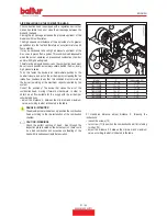
AIR REGULATION ON THE COMBUSTION HEAD
The combustion head is equipped with a regulation device that
makes it possible to open or close the air passage between the
disk and the head.
Closing the air passage increases the pressure upstream of the
disk also with low flow rates.
The high speed and turbulence of the air provides for its greater
penetration into the fuel and therefore an excellent mixture and
flame stability.
It may be necessary to have high air pressure upstream of the
disc, so as to prevent flame pulses. This condition is indispensable
when the burner operates on pressurised combustion chamber
and/or with high heating load.
Therefore the air regulation device on the combustion head must
be set to such position as to always obtain, behind the disc, a very
high pressure value.
To do this fasten the device in an intermediate position on the
head air closure, and act on the air damper by increasing the fan
intake flow; needless to say that this condition must occur when
the burner is working at the maximum capacity required by the
system.
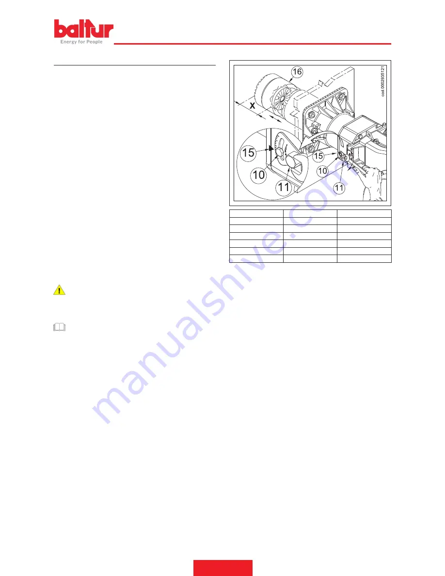
Correct the position of the device that closes the air of the
combustion head, moving it forward or backward, in order to
obtain an air flow suitable for the supply with the air damper
considerably open.
•
adjust the distance X between the minimum and maximum
value, according to what is indicated in the table.
DANGER / ATTENTION
The adjustments are indicative only; position the combustion
head according to the characteristics of the combustion
chamber.
CAUTION / WARNINGS
Check the perfect centring of head - disk through the
inspection glass located on the burner's scroll, there could
be a bad combustion and excessive overheating of the
head with its subsequent rapid deterioration.
Model
X
Index value (15)
TBG 85 ME
5 ÷ 36
1 ÷ 4,5
TBG 120 ME
17 ÷ 54
1 ÷ 5
TBG 150 ME
17 ÷ 36
1 ÷ 3,2
TBG 210 ME
14 ÷ 51
1 ÷ 5
TBG 260 ME
14 ÷ 51
1 ÷ 5
TBG 360 ME
12 ÷ 49
1 ÷ 5
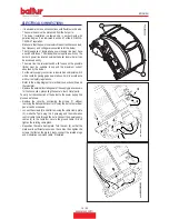
X = Head-disk distance; adjust distance X following the
instructions:
• loosen the screws (10),
•
turn screw (11) to position the combustion head (16) referring
to index (15).
•
adjust the distance X between the minimum and maximum
value, according to what is indicated in the table.
Summary of Contents for 17500010
Page 2: ......
Page 31: ...ITALIANO 29 32 0006081530_201711 SCHEMI ELETTRICI...
Page 32: ...ITALIANO 30 32 0006081530_201711...
Page 33: ...ITALIANO 31 32 0006081530_201711...
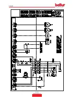
Page 63: ...ENGLISH 29 32 0006081530_201711 WIRING DIAGRAMS...
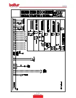
Page 64: ...ENGLISH 30 32 0006081530_201711...
Page 65: ...ENGLISH 31 32 0006081530_201711...
Page 67: ......


