background image

РОЗЖИГ И РЕГУЛИРОВКА

Проверьте,  чтобы  не  было  электрического  соединения 
(перемычки) между клеммами термостата второй ступени 
или, чтобы он не был соединенным. Отрегулируйте кулачок 
первой ступени так, чтобы воздушная заслонка поместилась в 
положение, которое вы считаете достаточным для того, чтобы 
проходило количество воздуха, соответствующее расходу 
топлива на первой ступени (смотрите 0002934230). Закройте 
главный выключатель, чтобы включить горелку. Подождите 
пока она не разгорится. В условиях работающей на первой 
ступени горелки откорректируйте (если требуется) подачу 
воздуха на соответствующем кулачке регулировки 1-ой ступени.  
Выполнив  регулировку,  отключите  горелку  и  включите, 
чтобы проверить хорош ли розжиг. Розжиг будет мягким, 
если количество подаваемого воздуха будет ограничено до 
возможного предела. Если розжиг мягкий, отключите горелку и 
выполните прямое соединение (перемычка) клемм термостата 
второй  ступени.  Отрегулируйте  на  соответствующем 
кулачке воздух для горения на положение, которое считаете 
подходящим для срабатывания второй ступени (смотрите 
0002934230). Вновь включите горелку, которая заработает 
на первой и на второй ступенях. Кулачком второй ступени 
отрегулируйте воздух, чтобы подогнать подачу к конкретным 
условиям. Горелка оснащена винтом регулировки положения 
диска пламени. Этот винт позволяет оптимизировать процесс 
горения, уменьшая воздушный зазор между диском и головкой. 

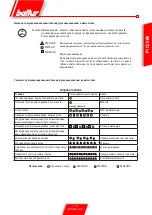
Модель горелки

ДАННЫЕ ПО РЕГУЛИРОВКЕ

ТИП ФОРСУНКИ

Давление 

насоса

Расход горелки

Регулировка 

воздушного 

сервопривода

Регулировка 

положения диска (Е)

GPH

бар

кг/ч

градусы

риска №

RINOX 190L2

1,75

10

6,30

2

2

18

8,25

50

2

2,50

10

8,80

5

4,5

18

11,80

60

4,5

3,00

10

10,80

8

7

18

14,60

70

7

Обычно зазор нужно уменьшить, если горелка работает с 
низким  расходом  топлива,  и  наоборот,  пропорционально 
увеличить, если расход топлива высокий (смотрите рис. N° 
0002934130). После того как вы изменили положение диска 
пламени, обычно требуется откорректировать положение 
воздуха на первой и второй ступенях, после чего  проверяется 
правильность розжига.

ПРИМ.  

РЕКОМЕНДУЕМЫЕ 

ФОРСУНКИ

DELAVAN типа W 60° 

DANFOSS типа H 60°

0002934130

D

  ΒΙΔΑ ΡΥΘΜΙΣΗΣ ΑΕΡΑ ΔΙΣΚΟΥ

E

  ΔΕΙΚΤΗΣ ΑΝΑΦΟΡΑΣ ΘΕΣΗΣ ΔΙΚΟΥ (0 = MIN; 7 = MAX)

ΡΥΘΜΙΣΗ ΚΑΥΣΗΣ

ПРИМ.:


Значения  в  таблице  относятся  к 

12% CO

2

  ( 4.5 O

2

 ), на уровне моря 

и при давлении в камере сгорания 

- 0.1 мбар.

ПРИМ.

Данные в таблице значения - приблизительные, 

лучших  эксплутационных  характеристик 

горелки можно добиться выполняя регулировку 

с учётом потребностей  котла.

11 / 16

0006080951_201401

PYCCKИИ

Summary of Contents for 35640050

Page 1: ...i per l uso RINOX 190 L2 Notice d instructions Manual de instrucciones ISTRUZIONI ORIGINALI IT ORIGINAL INSTRUCTIONS ARE IT INSTRUCCIONES ORIGINALES IT ISTRUCTIONS ORIGINALES IT IT 0006080951_201401 M...

Page 2: ......

Page 3: ...TBML Comist GI GI Mist Minicomist PYR RiNOx Spark Sparkgas TBG TBL TS IBR IB Variante LX per basse emissioni NOx rispettano i requisiti minimi imposti dalle Direttive Europee 2009 142 CE D A G 2004 10...

Page 4: ...libretto accompagni l apparecchio in modo che possa essere consultato dal nuovo proprietario e o dall installatore Per tutti gli apparecchi con optionals o kit compresi quelli elettrici si dovranno u...

Page 5: ...combustibile onde rimuovere eventuali residui che potrebbero compromettere il buon funzionamento del bruciatore Per la prima messa in funzione dell apparecchio far effettuare da personale professional...

Page 6: ...185 Trasformatore 35 mA 2x13 kV Potenza elettrica assorbita kW 0 230 Peso kg 18 Funzionamento Bistadio salto di pressione Assorbimento totale in fase di partenza con trasformatore d accensione inseri...

Page 7: ...2270800 Rev 17 11 2004 A A1 A2 B B1 B2 C D D F I I1 L L M N min max min max RINOX 190L2 300 158 145 345 275 93 620 100 250 100 165 165 150 200 M10 110 9 Elettrovalvole 10 Pompa gasolio 11 Motore 12 Fl...

Page 8: ...dopo la saracinesca si installa il filtro ed a questo si collega il flessibile di raccordo all aspirazione della pompa del bruciatore Filtro flessibile e relativi nippli di collegamento sono a corred...

Page 9: ...lla caldaia tramite i 4 prigionieri e i relativi dadi in dotazione N B Accertarsi che il cannotto penetri in camera di combustione come da disposizioni del costruttore della caldaia COLLEGAMENTI ELETT...

Page 10: ...oni se si dovesse ripetere ancora il dispositivo andr immediatamente in blocco Ad ogni intervento dei consensi W SB R il conteggio viene azzerato Lo sblocco del dispositivo di comando si ottiene preme...

Page 11: ...loro significato Indicazioni di funzionamento malfunzionamento e diagnostica TABELLA DI RIEPILOGO Condizioni Sequenza colori Colori Condizioni di attesa altri stadi intermedi Nessuna luce Preriscaldo...

Page 12: ...censione difettosit trasformatore di accensione 3 lampeggi On Disponibile 4 lampeggi On Luce estranea durante la fase di accensione 5 lampeggi On Disponibile 6 Lampeggi On Disponibile 7 lampeggi On As...

Page 13: ...atore che si rimette in funzione con la prima e seconda fiamma Agire sulla camma di regolazione aria di seconda fiamma per adeguare l erogazione della stessa alle condizioni specifiche Il bruciatore p...

Page 14: ...AGGIO VENTOLA Verificare in fase di montaggio ventola che sia rispettata la misura indicata in figura 0002934150 POMPA SUNTEC AT 3 45 A CON FILTRO INCORPORATO 1 Valvola solenoide di blocco per la funz...

Page 15: ...fano per l ispezione alla testata si deve smontare la piastra portacomponenti che pu essere appesa al corpo bruciatore in due posizioni per poter operare agevolmente Il motore il trasformatore l elett...

Page 16: ...atore scattato o mancanza di tensione in linea 4 La linea dei termostati non stata eseguita secondo schema o qualche termostato rimasto aperto 5 Guasto interno all apparecchiatura 1 Pressione di polve...

Page 17: ...lle camme agire sulle rispettive viti L indice dell anello rosso indica sulla rispettiva scala di riferimento l angolo di rotazione impostato per ogni camma SCHEMA ELETTRICO RINOX 190L2 H0 Lampada blo...

Page 18: ...30 13 95 14 57 15 17 15 74 16 29 16 83 17 34 17 85 18 34 18 81 19 28 3 50 4 00 12 72 13 60 14 42 15 20 15 94 16 65 17 33 17 99 18 62 19 23 19 82 20 40 20 95 21 50 22 03 4 00 4 50 14 31 15 30 16 22 17...

Page 19: ...N BT BTG BTL TBML Comist GI GI Mist Minicomist PYR RiNOx Spark Sparkgas TBG TBL TS IBR IB Variant LX with low NOx emissions respect the minimal regulation of the European Directives 2009 142 EC G A D...

Page 20: ...and leaves the equipment make sure that the booklet always goes with the equipment so it can be consulted by the new owner and or installer For all equipment with optionals or kits including electrica...

Page 21: ...IL OR OTHER FUEL SUPPLIES General warning notes Installation of the burner must be carried out by qualified technicians and in compliance with current law and regulations since incorrect installation...

Page 22: ...10 50Hz Motor kW 0 185 Tranformer 35 mA 2x13 kV Absobed electrical power kW 0 230 Weight kg 18 Operation Two stage pressure drop Total absorption at start with ignition transformer on STANDARD ACCESS...

Page 23: ...9 Electrovalves 10 Light oil pump 11 Motor 12 Burner connection flange 13 Insulating gasket 14 Air regulation servomotor N 0002270800 Rev 17 11 2004 OPERATING RANGE N 000292002 Rev 167 11 2004 A A1 A2...

Page 24: ...this which in turn should be connected to the suction of the burner pump Connect the flexible fitting to the return pipe after the gate valve and then connect it ot the pump return Filter flexible pi...

Page 25: ...er to the boiler via the 4 stud bolts and relative nuts supplied N B Make sure the tube penetrates into the combustion chamber as per the boiler manufacturer s instructions ELECTRICAL CONNECTIONS The...

Page 26: ...out a maximum of three repetitions and if there is still no flame the device will go immediately into lock out The count is reset at zero each time consents are given W SB R The control device is rel...

Page 27: ...colour sequences and their meanings Functioning malfunctioning and diagnostics indications No light RED YELLOW GREEN Legend Status Colour sequence Colours Waiting conditions other intermediate stages...

Page 28: ...ilable 10 flashes Off Electrical cabling problem or internal damage to the device Diagnoses of the causes of malfunction and lock out If there is a burner lock out there will be a continuous red light...

Page 29: ...rt operating with the 1st flame Operate the air regulation cam of the 2nd flame in order to obtain the quantity of air considered necessary for the specific conditions The burner is supplied with regu...

Page 30: ...asurements indicated in the diagram when fitting the fan FAN ASSEMBLY DIAGRAM SUNTEC PUMP MOD AT 3 45A WITH BUILT IN FILTER 1 Solenoid blocking valve for in line cutt off usually closed 1st flame 2 So...

Page 31: ...u must disassemble the component carrying plate which can be hung on hung on the burner body in two different positions to make work as practical as possible The motor transformer and solenoidvalveare...

Page 32: ...not start Defective flame with sparks Not well shaped flame with smoke and soot 1 Photoresistance is cut off or dirty with smoke 2 Boiler fouled 3 Photoresistor circuit failure 4 Dirty disk or mouth 1...

Page 33: ...ustment of the cams use use their screws The mark of the red ring indicates the rotation angle on the reference scale set for each cam ELECTRICAL DIAGRAM FOR RINOX 190L2 H0 Block lamp H1 Operation lig...

Page 34: ...13 30 13 95 14 57 15 17 15 74 16 29 16 83 17 34 17 85 18 34 18 81 19 28 3 50 4 00 12 72 13 60 14 42 15 20 15 94 16 65 17 33 17 99 18 62 19 23 19 82 20 40 20 95 21 50 22 03 4 00 4 50 14 31 15 30 16 22...

Page 35: ...s et industriels s ries BPM BGN BT BTG BTL TBML Comist GI GI Mist Minicomist PYR RiNOx Spark Sparkgas TBG TBL TS IBR IB Variante LX faibles missions NOx respectent les conditions minimales requises im...

Page 36: ...rnier toujours v rifier que la notice accompagne l appareil afin qu il puisse tre consulter par le nouveau pro pri taire et ou par l installateur Pour tous les appareils avec options ou kit y compris...

Page 37: ...rne soign de tous les tuyaux d arriv e du combustible afin d liminer les ventuels r sidus susceptibles de compromettre le bon fonctionnement du br leur Lors de la premi re mise en service de l apparei...

Page 38: ...Trasformateur 35 mA 2x13 kV Pussance lectrique absorb d kW 0 230 Poids kg 18 Fonctionnement Deux allures saut de pression Absorption totale en phase de d part avec transformateur d allumage enclench M...

Page 39: ...e 9 Electrosoupape 10 Pompe gas oil 11 Moteur 12 Bride de raccordement bruleur 13 Joint d tanch sit 14 Sevomoteur volet d air N 0002270800 Rev 17 11 2004 PLAGE D ULISATION N 000292002 Rev 167 11 2004...

Page 40: ...ble Au bout des canalisations rigides les vannes d arr t du combustible doivent tre install es Sur la canalisation d aspiration apr s la vanne on installe le filtre auquel est connect le flexible de r...

Page 41: ...ons et des crous relatifs fournis avec l appareil N B V rifier que le tube p n tre dans la chambre de combustion conform ment aux dispositions du constructeur de la chaudi re BRACHEMENTS LECTRIQUES Le...

Page 42: ...titions si le probl me persiste le dispositif se bloque imm diatement A chaque intervention des autorisations W SB R le comptage est remis z ro Pourd bloquerledispositifdecommande appuyerpendantenvir...

Page 43: ...nostic Rouge clignotante rapide Indications de fonctionnement mauvais fonctionnement et diagnostic Le bouton de d blocage EK est l l ment principal qui permet de suivre visuellement les conditions de...

Page 44: ...clignotements On Anomalie du temps de pr chauffage du combustible 9 clignotements On Disponible 10 clignotements Off Probl me de c blage lectrique ou d t rioration l int rieur du dispositif Diagnostic...

Page 45: ...nction avec la premi re et la seconde flamme Agir sur la came de r glage de l air de la seconde flamme afin d adapter le d bit de cette derni re aux conditions sp cifiques Le br leur est quip d une vi...

Page 46: ...N 8736 Lors de la phase de montage v rifier que la mesure indiqu e sur la figure est respect e SCHEMA DE MONTAGE VENTILATEUR 1 Sol noide d arr t pour la fonction de coupure en ligne nor malement ferm...

Page 47: ...pection de la t te il est n cessaire de d monter la plaque porte composants laquelle peut tre accroch e au corps br leur dans deux positions pour agir de la fa on la plus rationnelle possible Le moteu...

Page 48: ...Tension coup e car interrupteur g n ral ouvert ou interrupteur de maxima du compte heures d clench ou coupure de tension de ligne 4 La ligne des thermostats n est pas r alis e se lon sch ma ou un the...

Page 49: ...ge des cames agir sur le vis respectives L indice de la bague rouge indique l angle de rotation etablit pour chaque came sur l echelle respective de reference SCHEMA ELECTRIQUE RINOX 190L2 H0 Lampe bl...

Page 50: ...24 20 95 21 63 22 30 22 95 23 57 24 19 24 78 4 50 5 00 15 90 17 00 18 03 19 00 19 93 20 82 21 67 22 48 23 27 24 04 24 78 25 49 26 19 26 87 27 54 5 00 5 50 17 49 18 70 19 83 20 90 21 92 22 90 23 83 24...

Page 51: ...N BT BTG BTL TBML Comist GI GI Mist Minicomist PYR RiNOx Spark Sparkgas TBG TBL TS IBR IB Variante LX para bajas emisiones de NOx respetan los requisitos m nimos impuestos por las Directivas Europeas...

Page 52: ...el nuevo propietario y o instalador Para todos los aparatos con elementos opcionales o kits incluidos los el ctricos hay que utilizar solo accesorios originales QUEMADORES Esteaparatoest destinadosol...

Page 53: ...cimiento del combustible para evitar posibles residuos que podr an comprometer el buen funciona miento del quemador La primera vez que se pone en funcionamiento el aparato el personal cualificado prof...

Page 54: ...Transformador 35 mA 2x13 kV Potencia el ctrica absorbida kW 0 230 Peso kg 18 Foncionamiento De dos etapas salto de presi n Consumo total en fase de arranque con el transformador de encendido conectad...

Page 55: ...ia 9 Elettrov lvula 10 Bomba de gas leo 11 Motor 12 Brida de sujeci n del quemador 13 Junta aislante 14 Servomotor regulaci n del aire N 0002270800 Rev 17 11 2004 A A1 A2 B B1 B2 C D D F I I1 L L M N...

Page 56: ...n tener una buena estanqueidad se consigue con la utilizaci n del tubo de cobre o de acero de diametro adecuado Todos los extremos de la tuber a de aspiraci n despues de la compuerta de corte del comb...

Page 57: ...imo fijar el quemador a la caldera con los 4 pernos prisioneros y las tuercas en dotaci n Nota Asegurarse de que el soporte de las boquillas penetre en la c mara de combusti n como indica el fabricant...

Page 58: ...un m ximo de 3 repeticiones si se repite otra vez el dispositivo se bloquear inmediatamente Cada vez que intervienen los dispositivos W SB R se pone a cero la cuenta El desbloqueo del dispositivo de m...

Page 59: ...itencia r pida para diagn stico Rojo intermitente r pido Indicaciones de funcionamiento mal funcionamiento y diagn stico El bot n de desbloqueo EK es el elemento principal que permite tanto ver visual...

Page 60: ...je del quemador defectuoso 8 parpadeos On Anomal as del tiempo del precalentamiento del combustible 9 parpadeos On Disponible 10 parpadeos Off Problemas de cableado el ctrico o da os dentro del dispos...

Page 61: ...que se vuelve a poner en funcionamiento con la primera llama y la segunda Haga que el suministro de aire de 2 llama sea el adecxuado para las condiciones especificas mediante la leva de regulaci n de...

Page 62: ...34150 N 8736 Verificar durante la fase de montaje del ventilador que se respete la medida indicada en la figura ESQUEMA DE MONTAJE DEL VENTILADOR BOMBA SUNTEC AT 3 45A CON FILTRO INCORPORADO 1 V lvula...

Page 63: ...a placa que sujeta los portacomponentes para poder trabajar con la mayor facilidad posible esta placa puede colgarse al cuerpo del quemador de dos maneras diferentes El motor el transformador y la ele...

Page 64: ...mador no arranca Llama defectuosa con presencia de chispas Llama incorrecta con homo y hollin 1 Fotoresistencia interrumpida o sucia por humo 2 Caldera sucia 3 Circuito de la fotorresistencia averiado...

Page 65: ...nir en los respectivos tornillos El ndice del anillo rojo indica el ngulo de rotaci n que se ha establecido para cada leva en la respectiva escala de referencia ESQUEMA ELECTRICO RINOX 190L2 H0 L mpar...

Page 66: ...62 13 30 13 95 14 57 15 17 15 74 16 29 16 83 17 34 17 85 18 34 18 81 19 28 3 50 4 00 12 72 13 60 14 42 15 20 15 94 16 65 17 33 17 99 18 62 19 23 19 82 20 40 20 95 21 50 22 03 4 00 4 50 14 31 15 30 16...

Page 67: ...park Sparkgas TBG TBL TS IBR IB LX 2009 142 CE 2004 108 CE 2006 95 CE 2006 42 EN 676 2003 A2 2008 EN 267 2009 23 2013 CE0085 DVGW CERT GmbH Josef Wirmer Strasse 1 3 53123 10 4 6 7 8 11 12 SUNTEC AT 3...

Page 68: ...BALTUR 2 16 0006080951_201401 PYCCK...

Page 69: ...3 2 RC B 3 16 0006080951_201401 PYCCK...

Page 70: ...NOX 190L2 5 9 16 0 70 00 190 0 5 5 cst 20 C 1 5 E 20 C 1 230 10 50 0 185 35 A 2x13 0 230 18 RINOX 190L2 N 1 N 2 1 4 x3 8 x1200 N 4 M10 N 4 M10x50 N 4 M10 3 8 N 2 1 4 N 2 3 8 4 16 0006080951_201401 PYC...

Page 71: ...0002270800 A A1 A2 B B1 B2 C D D F I I1 L L M N min max min max RINOX 190L2 300 158 145 345 275 83 620 100 250 100 166 166 150 200 M10 110 1 2 3 7 4 5 6 7 8 9 10 11 12 13 14 5 16 0006080951_201401 PYC...

Page 72: ...H L 0 25 i 1 6 2 7 3 8 4 5 9 1 8 3 4 9 6 10 7 1 3 4 6 7 10 P 3 5 H L 10 12 0 5 26 54 1 24 47 1 5 18 38 2 14 30 2 5 10 23 3 6 15 3 5 7 H L 10 1 30 2 35 3 40 4 45 H L 10 1 30 2 35 3 40 4 45 6 16 0006080...

Page 73: ...N 0002934100 1 B C 2 E F 3 4 1 5 2 7 16 0006080951_201401 PYCCK...

Page 74: ...t1 t1 W SB R V t1 t3 TSA t3n BV1 BV2 t4 220 240 LMO 24 111B2 16 15 10 10 15 LMO LMO A B C D R tw t1 t3 TSA t3n t4 BV1 BV2 8 16 0006080951_201401 PYCCK...

Page 75: ...EK EK 5 tw 9 16 0006080951_201401 PYCCK...

Page 76: ...3 AL 10 2 TSA 3 4 5 6 7 3 8 9 10 AL 10 1 3 10 16 0006080951_201401 PYCCK...

Page 77: ...PH RINOX 190L2 1 75 10 6 30 2 2 18 8 25 50 2 2 50 10 8 80 5 4 5 18 11 80 60 4 5 3 00 10 10 80 8 7 18 14 60 70 7 N 0002934130 DELAVAN W 60 DANFOSS H 60 0002934130 D E 0 MIN 7 MAX 12 CO2 4 5 O2 0 1 11 1...

Page 78: ...A B C D RINOX 190L2 5 0 5 1 5 5 5 3 5 4 0002934112 0002934150 N 8736 SUNTEC AT 3 45A 3 55A 1 1 2 2 3 4 1 5 2 6 7 8 1 8 9 1 8 10 10 1 18 2 12 16 0006080951_201401 PYCCK...

Page 79: ...0002934140 12 1 A 2 6 B 3 4 C 13 16 0006080951_201401 PYCCK...

Page 80: ...1 2 3 4 1 2 3 4 5 6 1 2 3 4 5 6 1 2 3 4 5 1 2 3 4 1 2 3 4 1 2 3 4 1 2 3 4 5 6 1 2 3 4 5 6 1 2 3 4 5 1 2 3 4 1 2 3 4 14 16 0006080951_201401 PYCCK...

Page 81: ...02934230 02210881 STA13BO 2N36L 1 1 2 3 2 4 1 5 2 1 2 6 7 RINOX 190L2 H0 H1 H18 2 Y1 1 Y2 2 B1 TA TS TC T2 2 MV P1 A1 Y10 15 16 0006080951_201401 PYCCK...

Page 82: ...6 65 17 33 17 99 18 62 19 23 19 82 20 40 20 95 21 50 22 03 4 00 4 50 14 31 15 30 16 22 17 10 17 94 18 73 19 50 20 24 20 95 21 63 22 30 22 95 23 57 24 19 24 78 4 50 5 00 15 90 17 00 18 03 19 00 19 93 2...

Page 83: ......
Page 84: ...in esso riportato El presente cat logo tiene car cter puramente indicativo La Casa por lo tanto se reserva cualquier posibilitad de modificati n de datos t cnicos y otras anotaciones Ce manuel rev t...

Reviews: