•
The gas control pressure switch (minimum) prevents burner opera-
tion when gas pressure is not the foreseen one. It is clear from the
specific function of the pressure switches that the control pressure
switch for minimum pressure must make use of the contact that is
closed when the pressure switch detects pressure greater than that
for which it is regulated.
DANGER / ATTENTION
Once the adjusting operations are completed, visually check
that the thin plate on which the bearing acts has a progressive
profile. Also check trough the dedicated tools that during the
passage between 1st and 2nd stage the combustion parame-
ters do not excessively vary from the optimal values.
POWER AT START-UP
The standard EN 676 prescribes that for burners with maximum
output above 120 kW the ignition must occur at a reduced power
Pstart
than the maximum power of operation
Pmax
at which the
burner is calibrated.
Pstart
depends on the safety time of the burner equipment; in par-
ticular:
ts = 2s →
Pstart
≤ 0.5
x
Pmax
.
ts = 3s →
Pstart
≤ 0.333 x
Pmax
.
Example
if the maximum regulation power of the burner
Pmax
is
equal to 900 kW, it must be:
Pstart
≤ 450 kW where ts = 2s
Pstart
≤ 300 kW where ts = 3s
Check power at ignition
•
Disconnect the flame sensor wire (in this case the burner turns
on and goes into lock-out after the safety time ts).
•
Perform 10 consecutive ignitions and following block.
•
Measure at the meter the amount of gas burned
Qstart
[m³]
and check that
Qstart ≤ Pmax /360
( in m³/h)
Example
Pmax = 90 m³/h (about 900 kW with natural gas)
After 10 ignitions with the related lock out, the gas consumption read
on the meter must be:
Qstart
≤ 90/360 = 0.25 [m³]
If this does not occur, reduce the flow of gas to the ignition through
the brake of the valve.
UV PHOTOCELL
The UV photocell does not detect daylight or the light from a common
lamp. Sensitivity can be checked with a flame (cigarette lighter, cand-
le) or with the electric discharge between the electrodes of a common
ignition transformer. To ensure proper operation, the UV photocell
current value should be sufficiently stable and should not drop below
the minimum value required by the specific equipment; this value is
indicated in the wiring diagram. It may be necessary to tentatively
find the best position by sliding (axial or rotational movement) the
casing that contains the photocell with respect to the fastening clamp.
This can be checked by connecting a micro-ammeter, with a suitable
scale, in series to one of the two UV photocell connection cables.
Obviously the + and - polarity must be respected. The ...equipment
needs a photocell current between 200 and 500 microA.
Even the slightest greasiness will compromise the passage of rays
through the photocell bulb, thus preventing the sensitive internal ele-
ment from receiving the quantity of radiation necessary for it to work
properly. If the bulb is fouled with diesel, fuel oil, etc... it must be
properly cleaned.
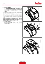
CAUTION / WARNINGS
Even simply touching the bulb with fingers may leave a slight
greasiness which could compromise photocell operation.
display_TBML_001
1
2
3
4
5
7
8
1
6
9
1 ON / OFF main switch
2 Fuel switch.
3 Liquid fuel operation warning light.
4 Gaseous fuel operation warning light.
5 Equipment shut-down warning light.
6 Equipment release button.
7 Voltage warning light.
8 Fusibile.
9 Fuel loading button.
ENGLISH
27 / 42
0006160079_202008
Summary of Contents for 56510010
Page 2: ......
Page 42: ...SCHEMI ELETTRICI ITALIANO 40 42 0006160079_202008...
Page 44: ...ITALIANO 42 42 0006160079_202008...
Page 84: ...WIRING DIAGRAMS ENGLISH 40 42 0006160079_202008...
Page 86: ...ENGLISH 42 42 0006160079_202008...
Page 87: ......


