CONTROLS
•
After starting up the burner, check the safety devices (flame detec-
tor, lock-out system, thermostats)
•
The flame control device should trip if the flame extinguishes during
operation (this check should be made after at least 1 minute after
ignition)
•
The burner must shut down in lock position and remain in that con-
dition when, upon ignition and during the time preset by the com-
mand equipment, the flame is not ignited. The lock-out causes the
immediate stop of the motor and burner and the switching on of the
corresponding lock-out light indication. To check the efficiency of
the flame detector and lock-out system, proceed as follows:
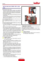
- Start the burner.
- After at least one minute, remove the flame detector from its
housing and simulate flame failure (use a rag to close the speci-
fic opening on the flame detector). The burner flame should go
to out. The equipment goes into lock-out within the time pre-set
by the programme. The equipment can be reset only manually
by pressing the specific button.
AIR REGULATION ON THE COMBUSTION HEAD
The combustion head is equipped with a regulation device that makes
it possible to open or close the air passage between the disk and
the head. Closing the passage increases the pressure upstream of
the disk also with low flow rates. The high speed and turbulence of
the air provides for its greater penetration into the fuel and therefore
an excellent mixture and flame stability. High air pressure upstream
of the disk may be necessary to prevent flame fluctuations, this is
particularly essential when the burner works on the furnace that is
pressurised and/or at a high thermal load.
The combustion head closing device must be set to a position in whi-
ch, behind the disc, there is always a very high air pressure value.
When the burner operates at maximum delivery, adjust the head air
closure, in such a way as to require a considerable air flow damper
opening. Therefore start the regulation with the device that closes
the air on the combustion head in an intermediate position, igniting
the burner for an indicative regulation as explained above. Move the
combustion head forward or backward so as to have an air flow sui-
table for the delivery.
CAUTION / WARNINGS
The above adjustments are only indicative; position the com-
bustion head according to the characteristics of the furnace.
•
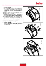
Loosen the screw (1)
•
Turn screw (2) to position the combustion head (3), referring to
index (4)
•
Adjust the distance (x) between the minimum and maximum ac-
cording to the indications in the table
BURNER
X
Value indicated by index 4
TBML 90P
68 ÷ 84
3 ÷ 1
TBML 150P
94 ÷ 130
5 ÷ 1
ENGLISH
28 / 42
0006160079_202008
Summary of Contents for 56510010
Page 2: ......
Page 42: ...SCHEMI ELETTRICI ITALIANO 40 42 0006160079_202008...
Page 44: ...ITALIANO 42 42 0006160079_202008...
Page 84: ...WIRING DIAGRAMS ENGLISH 40 42 0006160079_202008...
Page 86: ...ENGLISH 42 42 0006160079_202008...
Page 87: ......

