17 / 42
0006080764 _201312
ENGLISH
IGNITION ANd AdJUSTMENT
WITH LIqUId FUEL
• Check that the characteristics of the nozzle (delivery and spray
angle) are suitable for the furnace (see BT 9353/1). If not,
replace it.
• Check that the tank is filled with fuel and that it is, at least visually,
suitable for the burner.
• Check that there is water in the boiler and that the gates on the
system are open.
• Make sure that the products of combustion can be released
freely (boiler and chimney gates open).
• Make sure that the voltage of the electric line to which the
burner is to be connected, corresponds to that requested by the
manufacturer, and that the motor’s electrical connections have
been correctly prepared to match the voltage rating available.
Also check that all electric connections made on-site are
performed correctly as shown in our wiring diagram.
• Make sure that the combustion head enters the furnace to the
extent specified by the boiler manufacturer.
• Remove the protective cover from the rotating disk inserted on
the servomotor which regulates delivery (fuel/air). On this disk
have been fitted adjustable screws which are used to control
the fuel and the relative comburent air.
• Check that the air regulation device on the combustion head
is in the position considered necessary for the fuel delivery
required (the air passage between the disk and the head should
be considerably closed when the fuel delivery is considerably
reduced; on the other hand, when the nozzle has a fairly high
delivery, the air passage between the disk and the head should be
relatively open) see Chapter “Regulation of the Combustion Head”.
• Turn the two modulation switches to “MIN” (minimum) and
“MAN” (manual).
• Start up the fuel supply auxiliary circuit, check its efficiency and
regulate the pressure at about 1 bar (if the circuit is supplied
with a pressure regulator).
• Remove the vacuum gauge connection point plug from the
pump, then slightly open the gate on the fuel pipe. Wait for the
fuel to flow out of the hole without air bubbles and close the
damper.
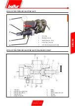
• Fit a manometer (full scale about 3 bar) to the pump vacuum
gauge connection point to check the pressure value at which the
fuel reaches burner pump. Insert a manometer (full scale about
30 bar) into the manometer connection point provided on the
pump and control its working pressure. Fit a pressure gauge (full
scale about 30 bar) in the first flame return pressure regulator
connection point (see 0002900311) to check the return pressure.
• Now open all gates and any other shut-off element on the
diesel pipes.
• Put the switch on the control panel in the “O” (open) position
and power the electric line which the burner is connected to.
Manually press the specific remote control switches to check
that the fan and pump motors turn in the correct sense, and if
necessary change the position of two cables of the main line to
invert the rotation sense.
• Start the burner pump by manually pressing the relevant remote
control switch until the pump pressure gauge detects a slight
pressure. The presence of low pressure in the circuit confirms
that filling up has taken place.
• Insert the switch on the control panel to give current to the control
box. If the thermostats and pressure switches (safety and boiler)
are closed, the control box’s programmer will be connected and
will enable the burner’s component devices according to its pre-
established programme. The equipment turns on as described
in the chapter “Operation description”.
To adjust the gas pilot flame proceed as follows:
- disconnect the wire from terminal no. 18 of the LFL... unit to
prevent the electromagnet being switched on.
- Disconnect the wire at terminal no. 17 (intermittent pilot flame)
from the terminal of the LFL...unit and connect it to terminal
no. 18 (continuous pilot flame).
- Ignite the burner, adjust the quantity of gas and air for the pilot
flame and check for proper ignition several times.
- When adjustment is over restore the original connections.
• UV PHOTOCELL
If the pilot flame is detected by the UV photocell remember
what specified below A slight amount of grease will strongly
compromise the passage of the ultraviolet rays through the
UV photocell bulb, preventing the internal sensitive element
from receiving the quantity of radiations required for proper
operation. If the bulb is smeared with light oil, heavy oil, etc.
it must be cleaned thoroughly. Even contact with the fingers
can leave a slight greasy film, enough to affect the function
of the UV photocell. The UV photocell does not “see” daylight
nor does it perceive the light of an ordinary lamp. Sensitivity
can be checked with a flame (cigarette lighter, candle) or
with the electric discharge between the electrodes of a
common ignition transformer. To ensure a proper operation,
the UV photocell current value must be sufficiently stable
and not go below the minimum value required for the specific
equipment. It may be necessary to tentatively find the best
position by sliding (axial or rotational movement) the casing
that contains the photocell with respect to the fastening clamp.
This can be checked by connecting a micro-ammeter, with a
suitable scale, in series to one of the two UV photocell connection
cables. Obviously the polarity (+ and -) must be respected. The
photocell current value required for a correct operation of the
equipment is indicated in the wiring diagram.
• When the burner is working at “minimum” adjust the air according
to the amount needed to ensure good combustion. Unscrew or
screw the adjustable screws at the point of contact with the lever
that transmits the movement of the combustion air regulation
shutter. We recommend to keep the air quantity at a low level
when working at the “minimum” output to ensure a perfect ignition
even in the most difficult conditions.
• After adjusting the air for the “minimum” turn the modulation
switches to position “MAN” and to position “MAX”.
Summary of Contents for 66875410
Page 2: ......
Page 37: ...35 42 0006080764 _201312 ITALIANO schema elettrico...
Page 38: ...36 42 0006080764 _201312 ITALIANO...
Page 39: ...37 42 0006080764 _201312 ITALIANO...
Page 40: ...38 42 0006080764 _201312 ITALIANO...
Page 41: ...39 42 0006080764 _201312 ITALIANO...
Page 42: ...40 42 0006080764 _201312 ITALIANO...
Page 43: ...41 42 0006080764 _201312 ITALIANO RAMPA PILOTA RAMPA PRINCIPALE...
Page 46: ...2 42 0006080764 _201312 ENGLISH...
Page 79: ...35 42 0006080764 _201312 ENGLISH Wiring diagram...
Page 80: ...36 42 0006080764 _201312 ENGLISH...
Page 81: ...37 42 0006080764 _201312 ENGLISH...
Page 82: ...38 42 0006080764 _201312 ENGLISH...
Page 83: ...39 42 0006080764 _201312 ENGLISH...
Page 84: ...40 42 0006080764 _201312 ENGLISH...
Page 85: ...41 42 0006080764 _201312 ENGLISH PILOT TRAIN MAIN TRAIN...
Page 87: ......

