24 / 42
0006080764 _201312
N° 0002933441
N°0002933600
ENGLISH
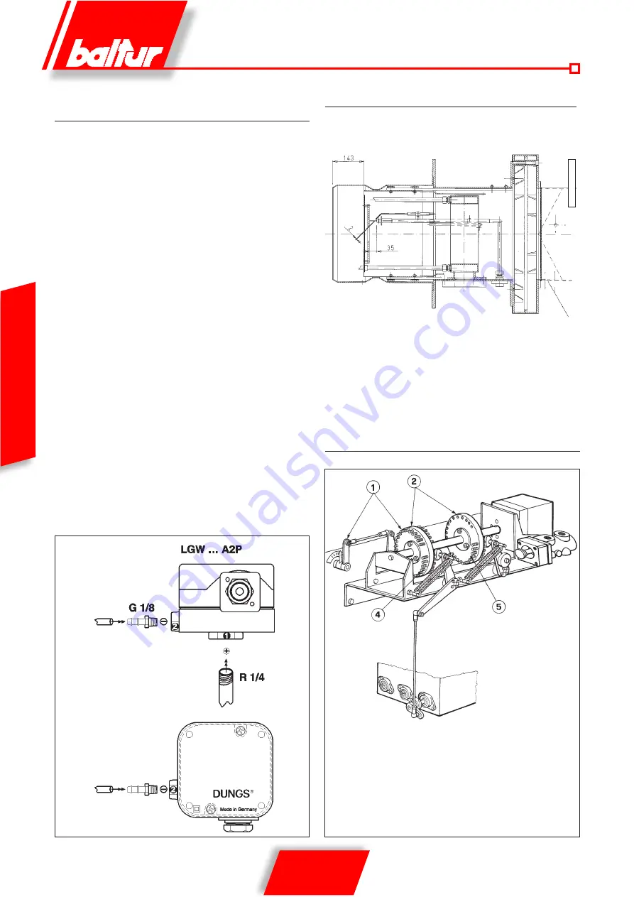
DESCRIPTION OF THE WORKING OF THE
DIFFERENTIAL AIR PRESSURE SWITCH
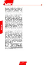
The air pressure switch stops the equipment operation if air pressure
is not at the expected value. The pressure switch must therefore
be adjusted so that it is triggered to close the NO contact (normally
open) when the air pressure in the burner reaches a particular value.
The connection circuit of the pressure switch is self-controlling so
that the NC contact (normally closed) which is meant to be closed
at rest (with the fan stopped and consequent lack of air pressure in
the burner), must actually achieve this condition, if it does not the
command and control equipment is not switched on (the burner is
stopped). Specifically, if the NO contact is not closed (normally open)
as it should be during working (this may be due to insufficient air
pressure), the equipment carries out its working cycle but does not
switch on the ignition transformer and does not open the gas pilot light
valve so the burner shuts down. Regulation prior to burner ignition:
adjust the pressure switch at minimum. Adjustment after burner
calibration: connect a manometer to the pressure switch’s positive
(+) pressure intake and another manometer to the pressure switch’s
negative pressure (-) intake. Check at which point in the modulation
there is the smallest pressure difference (∆ p) and adjust the
pressure switch to the midpoint of this difference. Example: positive
value + 1.5 mbar , negative value – 0.5 mbar, diff2 mbar,
setting 2:2 = 1 mbar.
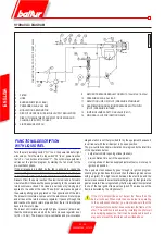
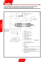
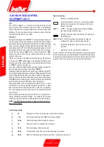
GAS PILOT ADJUSTMENT PRINCIPLE DIAGRAM
1 Adjustment screws for opening and closing air supply to head
2 Modulation discs
4 Adjustment screws for combustion air supply regulation
5 Fuel regulation screws
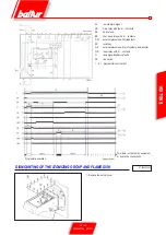
DETAIL OF BURNER MODULATION
UNIT WITH SERVOMOTOR
Summary of Contents for 66875410
Page 2: ......
Page 37: ...35 42 0006080764 _201312 ITALIANO schema elettrico...
Page 38: ...36 42 0006080764 _201312 ITALIANO...
Page 39: ...37 42 0006080764 _201312 ITALIANO...
Page 40: ...38 42 0006080764 _201312 ITALIANO...
Page 41: ...39 42 0006080764 _201312 ITALIANO...
Page 42: ...40 42 0006080764 _201312 ITALIANO...
Page 43: ...41 42 0006080764 _201312 ITALIANO RAMPA PILOTA RAMPA PRINCIPALE...
Page 46: ...2 42 0006080764 _201312 ENGLISH...
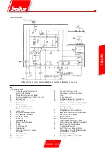
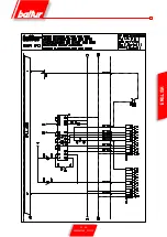
Page 79: ...35 42 0006080764 _201312 ENGLISH Wiring diagram...
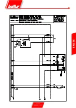
Page 80: ...36 42 0006080764 _201312 ENGLISH...
Page 81: ...37 42 0006080764 _201312 ENGLISH...
Page 82: ...38 42 0006080764 _201312 ENGLISH...
Page 83: ...39 42 0006080764 _201312 ENGLISH...
Page 84: ...40 42 0006080764 _201312 ENGLISH...
Page 85: ...41 42 0006080764 _201312 ENGLISH PILOT TRAIN MAIN TRAIN...
Page 87: ......

