26 / 42
0006080764 _201312
N° 0002910930
ENGLISH
GAS PRESSURE SWITCH FUNCTIONAL DESCRIPTION
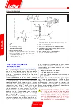
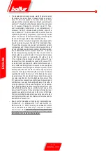
The gas pressure control switches (minimum and maximum) prevent the burner
from operating when gas pressure is not between the expected range. The specific
function of the pressure switches clearly reveals that the pressure switch for controlling
minimum pressure uses the NO (normally open) contact which closes when the
pressure switch detects a pressure value above the value it is set to, while the pressure
switch for controlling maximum pressure uses the NC (normally closed) contact that
is closed when the pressure switch detects a pressure lower than the value it is set
to. The minimum and maximum gas pressure switches must be set when testing the
burner, on the basis of the pressure measured in each case. The pressure switches
are connected in series, therefore operation (i,e, opening of the circuit) of the switches
while burner is operating (flame lit), will cause the burner to stop immediately.
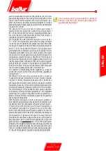
Regulation prior to burner ignition: regulate the pressure switch for minimum pressure
at the minimum value of the scale, regulate the pressure switch for the maximum
value at the maximum value of the scale.
Regulation after the burner calibration: With the burner at the maximum delivery,
regulate the pressure switch for minimum pressure by increasing the regulation value
until the burner shuts down, read the value on the regulation ferrule and set it to a value
diminished by 5 mbar. With the burner off, regulate the pressure switch for maximum
pressure, diminishing the regulation value until the NC (normally closed) contact opens.
Read the value on the regulation ferrule and set it to a value increased by 5 mbar.
In case only one pressure switch is installed on the gas ramp, it must be a pressure
switch for minimum pressure.
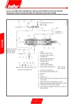
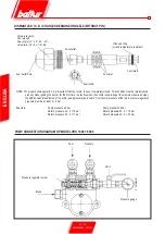
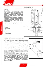
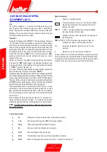
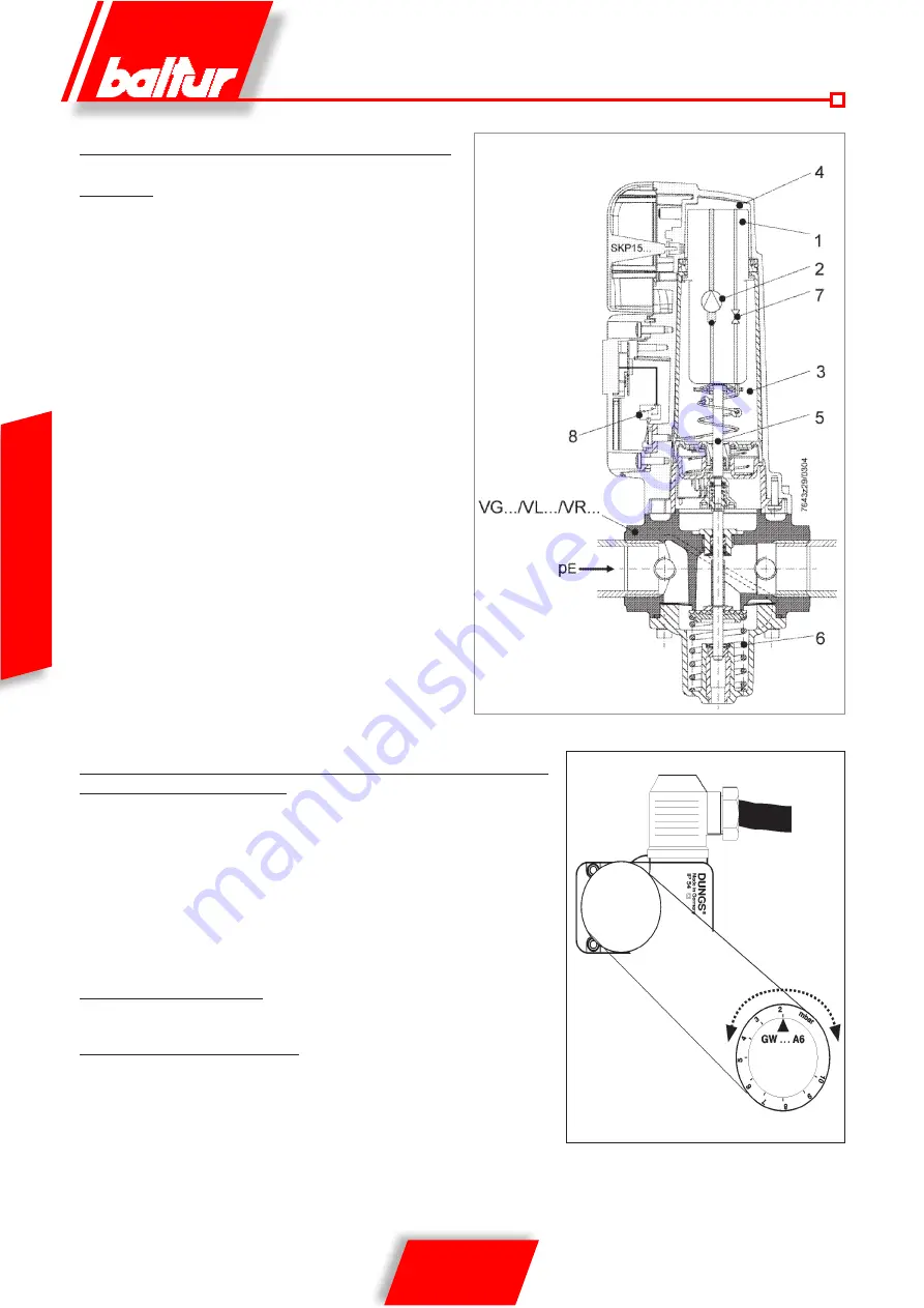
SKP 15... complete with valve
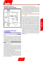
SKP 15,000 E2 GAS VALVE
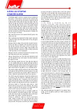
OPERATION
One-stage valves
In the case of a valve opening signal, the pump turns on and the
magnetic valve closes. The pump transfers the volume of oil located
under the piston in its upper section, the piston moves downward
and presses the closing return spring through the stem and the plate.
The valve stays in the open position and the pump and magnet
valve remain powered.
In the case of a closing signal (or due to a loss of voltage) the pump
stops, the magnetic valve opens permitting the decompression of the
piston’s upper chamber. The plate is pushed closed by the force of
the return spring and the gas pressure. The valves are completely
closed within 0.6 seconds.
This type of valve does not have gas output regulation (closed/open
version).
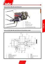
1 Piston
2 Oscillating pump
3 Oil reservoir
4 Pressure chamber
5 Shaft
6 Closing spring
7 Main valve
8 Limit switch (optional)
Summary of Contents for 66875410
Page 2: ......
Page 37: ...35 42 0006080764 _201312 ITALIANO schema elettrico...
Page 38: ...36 42 0006080764 _201312 ITALIANO...
Page 39: ...37 42 0006080764 _201312 ITALIANO...
Page 40: ...38 42 0006080764 _201312 ITALIANO...
Page 41: ...39 42 0006080764 _201312 ITALIANO...
Page 42: ...40 42 0006080764 _201312 ITALIANO...
Page 43: ...41 42 0006080764 _201312 ITALIANO RAMPA PILOTA RAMPA PRINCIPALE...
Page 46: ...2 42 0006080764 _201312 ENGLISH...
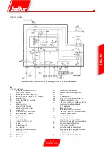
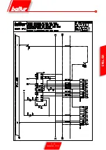
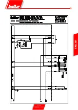
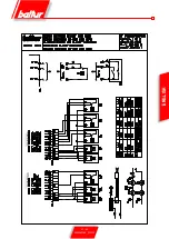
Page 79: ...35 42 0006080764 _201312 ENGLISH Wiring diagram...
Page 80: ...36 42 0006080764 _201312 ENGLISH...
Page 81: ...37 42 0006080764 _201312 ENGLISH...
Page 82: ...38 42 0006080764 _201312 ENGLISH...
Page 83: ...39 42 0006080764 _201312 ENGLISH...
Page 84: ...40 42 0006080764 _201312 ENGLISH...
Page 85: ...41 42 0006080764 _201312 ENGLISH PILOT TRAIN MAIN TRAIN...
Page 87: ......

