28 / 42
0006080764 _201312
ENGLISH
N° B
T 8
56
2/
2
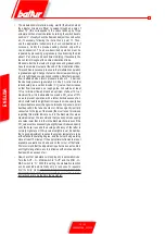
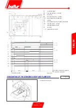
dETAILS OF THE MOdULATION
CONTROL MOTOR SqM 10 ANd SqM
20 FOR REGULATION OF CAMS
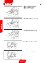
Use the corresponding red rings (A - Z - M) to modify the adjustment
of the 3 used cams.
Pushing with sufficient force in the desired direction, each (red) ring
can turn with respect to the reference scale. The index on the red
ring indicates on the respective reference scale the rotation angle
set for each cam.
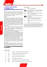
CONTROL ANd COMMANd
EqUIPMENT LFL 1,333 ..
Command and control equipment for mid and large output blown-
air burners (intermittent service *) for 1 or 2 stage burners or for
modulating burners with air pressure monitoring for air shutter
control. The command and control equipment feature the EC mark
according to the Gas and Electromagnetic Compatibility Directive.
*
For safety reasons, it is important to perform a
controlled stop each 24 hours!
As regards the standards
The following
LFL1.... features fully comply with the Standards
and ensure an extremely high safety level:
- The flame detector test and the false flame test start
immediately after the allowed post-combustion time. If the
valves remain open, or do not close immediately after the
regulation stop, a shutdown in lock condition is triggered
at the end of the allowed post-combustion time. The tests
finish only at the end of the pre-ventilation time of the next
start-up.
- The operation validity of the flame control circuit is verified
upon each burner start-up.
- The fuel valve control contacts are checked for wear during
the post-ventilation time.
- One fuse integrated in the equipment protects the control
contacts against possible overloads.
As for the burner control
- The equipment allows operation with or without post-
ventilation.
- Air gate controlled activation to ensure pre-
v e n t i l a t i o n w i t h n o m i n a l a i r f l o w r a t e .
Controlled positions: CLOSED or MIN (position of ignition
flame on start-up); OPEN at the beginning and MIN at the
end of the pre-ventilation time. If the servomotors fail to
position the air gate in the preset points, the burner does
not start.
- Ionization current minimum value = 6µA
- UV cell current minimum value = 70 µA
- Phase and neutral must never be inverted.
- Any place may be used for installation and assembly (IP40
protection class)
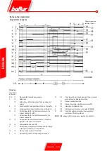
R e f e r e n c e
index
Camshaft
Adjustable Cams
Maximum air opening
- end of stroke
Total air closure
(burner off)
Air ignition
opening
B = On and off lever for motor - camshaft
coupling.
Position 1 = disabled
Position 2 = enabled
Summary of Contents for 66875410
Page 2: ......
Page 37: ...35 42 0006080764 _201312 ITALIANO schema elettrico...
Page 38: ...36 42 0006080764 _201312 ITALIANO...
Page 39: ...37 42 0006080764 _201312 ITALIANO...
Page 40: ...38 42 0006080764 _201312 ITALIANO...
Page 41: ...39 42 0006080764 _201312 ITALIANO...
Page 42: ...40 42 0006080764 _201312 ITALIANO...
Page 43: ...41 42 0006080764 _201312 ITALIANO RAMPA PILOTA RAMPA PRINCIPALE...
Page 46: ...2 42 0006080764 _201312 ENGLISH...
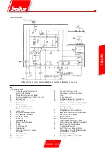
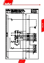
Page 79: ...35 42 0006080764 _201312 ENGLISH Wiring diagram...
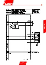
Page 80: ...36 42 0006080764 _201312 ENGLISH...
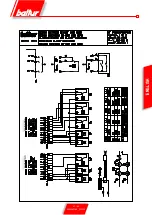
Page 81: ...37 42 0006080764 _201312 ENGLISH...
Page 82: ...38 42 0006080764 _201312 ENGLISH...
Page 83: ...39 42 0006080764 _201312 ENGLISH...
Page 84: ...40 42 0006080764 _201312 ENGLISH...
Page 85: ...41 42 0006080764 _201312 ENGLISH PILOT TRAIN MAIN TRAIN...
Page 87: ......

