32 / 42
0006080764 _201312
ENGLISH
GAS VALVE SEAL CONTROL
EqUIPMENT LdU 11...
Use
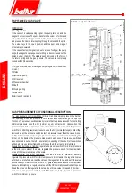
The LDU 11 equipment.... is used to check the gas burner valve
seal. Together with a standard pressure switch, it automatically
checks the gas burner valve seal before each start-up or after each
shutdown. The seal is checked in two pressure phases of the gas
circuit between the burner two valves.
Operation
During the first phase, called
“TEST 1”
, the pipe between the valves
to be checked must be at atmospheric pressure. In plants without
atmospheric pressure setting pipe, this condition is achieved through
the seal control equipment which opens the furnace side valve for 5
seconds during the
“t4”
time. When the pressure has been set to the
atmospheric value for 5 seconds, the furnace side valve is closed.
During the first phase
(TEST 1)
the control equipment
“DW”
pressure switch checks that the atmospheric pressure is kept
constant in the pipe.
If there is a blow-by in the safety valve while closing, the pressure
increases, the
“DW”
switch triggers, the equipment indicates such
increase and enters in fault state and the position indicator blocks
in
“TEST 1”
position (red light on).
Vice-versa, if the valve is tight and the pressure remains constant, the
device immediately sets the second phase
“TEST 2”.
In these conditions the safety valve opens for 5 seconds during the
“t3”
time introducing the gas pressure in the pipe (“filling operation”). During
the second phase the pressure must remain constant. If it decreases,
the burner furnace side valve features a blow-by while closing (fault),
the
“DW”
pressure switch triggers, and the control device inhibits the
burner start-up and stops in shutdown state (red light on).
If the second phase check is successful, the LDU 11 device.... closes
the internal circuit across terminals
3
and
6
(terminal
3 -
contact
ar2 -
external U-bolt of terminals
4
and
5 -
contact III - terminal
6).
This circuit usually gives the consensus to the equipment start-up
control circuit.
After terminals
3
and
6
circuit closure the LDU 11 programmer...
returns in stand-by position and stops, i.e. is ready for a new check
without changing the position of the programmer control contacts.
NOTE:
Set “DW” pressure switch to a value of about a half of the
gas system pressure.
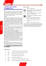
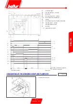
Symbol meaning:
}
Start-up = operating position
In systems without vent valve = test circuit put under
atmospheric pressure by the opening of the burner
furnace side valve.
TEST 1
“TEST 1 “ piping at atmospheric pressure (leakage
test upon closing of safety valve).
Test gas circuit put under pressure by the opening of
the safety valve.
TEST 2
TEST 2 “TEST 2” pipeline at gas pressure (blow-by
verification of valve on furnace side of burner).
I I I
Automatic programmer return to zero (or to rest
position).
}
Operation = set for new blow-by verification.
In case of fault, the control device terminals are not powered, except
terminal 13 which gives remote indication of the fault. After the check,
the programmer automatically returns to the stand-by position and is
preset to carry out a new gas valve seal test (while closing).
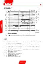
Control programme
t
4
5s
Putting the circuit to be tested under atmospheric pressure
t
6
7,5s
Time between start-up and “
AR
” main relay excitation
t
1
22,5s
1
st
check phase with atmospheric pressure
t
3
5s
Put gas circuit to be checked under pressure
t
2
27,5s
2nd check phase with gas pressure
t
5
67,5s
Total duration of seal test, up to burner operation consensus
t
20
22,5s
Return to the programmer stand-by position = preset for a new check.
Summary of Contents for 66875410
Page 2: ......
Page 37: ...35 42 0006080764 _201312 ITALIANO schema elettrico...
Page 38: ...36 42 0006080764 _201312 ITALIANO...
Page 39: ...37 42 0006080764 _201312 ITALIANO...
Page 40: ...38 42 0006080764 _201312 ITALIANO...
Page 41: ...39 42 0006080764 _201312 ITALIANO...
Page 42: ...40 42 0006080764 _201312 ITALIANO...
Page 43: ...41 42 0006080764 _201312 ITALIANO RAMPA PILOTA RAMPA PRINCIPALE...
Page 46: ...2 42 0006080764 _201312 ENGLISH...
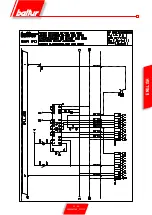
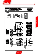
Page 79: ...35 42 0006080764 _201312 ENGLISH Wiring diagram...
Page 80: ...36 42 0006080764 _201312 ENGLISH...
Page 81: ...37 42 0006080764 _201312 ENGLISH...
Page 82: ...38 42 0006080764 _201312 ENGLISH...
Page 83: ...39 42 0006080764 _201312 ENGLISH...
Page 84: ...40 42 0006080764 _201312 ENGLISH...
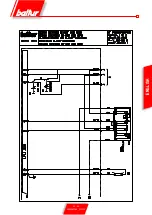
Page 85: ...41 42 0006080764 _201312 ENGLISH PILOT TRAIN MAIN TRAIN...
Page 87: ......

