8 / 42
0006080764 _201312
ENGLISH
dESCRIPTION OF THE
INdUSTRIAL BURNERS
The
GI 1000
burner is a packaged version made up of separately
supplied units; these components must be connected at the burner
installation site in full observance of the instructions given
z
.
A
- Combustion head with electric fan
B
- Power board
C
- Pumping unit for liquid fuels. If heavy oil is to be used this unit
also includes an electric heavy oil preheater and, on request,
an auxiliary steam preheater.
D
- Gas valve unit for burners employing gaseous fuels (usually
methane).
These burners are available in a range of versions to suit the
employed fuel type.
- (Methane)
GAS
-
DIESEL OIL
-
FUEL OIL
(max. 50°E nominal viscosity at 50°C )
- GAS
(Methane) /
FUEL OIL
(max. 5°E at 50°C nominal viscosity)
- GAS
(Methane) /
DIESEL OIL
Note that the
GI-Mist 1000 DSPGM and GI-Mist 1000 DSPNM
burners have been designed for operation with methane gas or
with liquid fuel.
-
“GI 1000”
series burners are modulating with a modulating
range of 1 - 4. Adaptation to the momentary thermal requirement
is done using a servomotor that regulates the quantity of
comburent air and fuel in a combined manner upon the
command of the probe in the boiler.
- The burner is fitted with a device that automatically varies
the cross-section of the air passage in the combustion head,
doing so proportionately to variations in load. This device gives
optimum combustion under all load conditions as a result of
optimisation of the air/fuel mix: this results in a reduced excess
of air and a better quality combustion.
FIxING BURNER TO BOILER
- Make a hole in the iron plate of the boiler in respect to the drill plate,
- Fix the stud bolts supplied with the accessories. It is advisable to
electrically solder the bolts to the internal part of the plate to avoid
losing them, such as in the event of the disassembly of the burner.
- If the iron plate doesn’t have insulation protection, it is necessary
to fit insulation protection between the iron plate and the boiler that
is at least 10 mm thick.
Make sure that the combustion head
penetrates the furnace to the extent requested by the boiler
manufacturer.
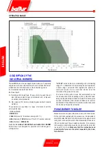
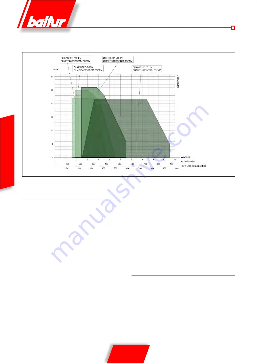
OPERATING RANGE
Pressure in the combustion chamber
Thermal power
Diesel
Summary of Contents for 66875410
Page 2: ......
Page 37: ...35 42 0006080764 _201312 ITALIANO schema elettrico...
Page 38: ...36 42 0006080764 _201312 ITALIANO...
Page 39: ...37 42 0006080764 _201312 ITALIANO...
Page 40: ...38 42 0006080764 _201312 ITALIANO...
Page 41: ...39 42 0006080764 _201312 ITALIANO...
Page 42: ...40 42 0006080764 _201312 ITALIANO...
Page 43: ...41 42 0006080764 _201312 ITALIANO RAMPA PILOTA RAMPA PRINCIPALE...
Page 46: ...2 42 0006080764 _201312 ENGLISH...
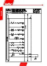
Page 79: ...35 42 0006080764 _201312 ENGLISH Wiring diagram...
Page 80: ...36 42 0006080764 _201312 ENGLISH...
Page 81: ...37 42 0006080764 _201312 ENGLISH...
Page 82: ...38 42 0006080764 _201312 ENGLISH...
Page 83: ...39 42 0006080764 _201312 ENGLISH...
Page 84: ...40 42 0006080764 _201312 ENGLISH...
Page 85: ...41 42 0006080764 _201312 ENGLISH PILOT TRAIN MAIN TRAIN...
Page 87: ......

