12 / 42
0006080764 _201312
N° 0
00
29
01
22
0
ENGLISH
FUNCTIONAL dESCRIPTION
WITH LIqUId FUEL
Turn the main isolating switch “q1” to on: the power indicator light
will come on. Turn the start / stop switch “S1” to on: power reaches
the “LFL ...” control box at terminal “1” . The cyclic relay equipment
carries out the ignition program by starting the fan motor for the
pre-ventilation phase.
If the air pressure provided by the fan is enough to cause the
corresponding pressure switch to intervene, it will do so immediately, as
well as the motor of the pump that sends the diesel oil to the burner ducts.
Diesel oil from the pump reaches the atomizer unit and is forced to
circulate within it because the passage leading to the outward and
return nozzles are closed. This closure is carried out by “closing pins”
applied to the ends of the rods. These “pins” are pressed against
the seats by strong springs placed on the opposite end of the rods.
The diesel oil circulates, comes out of the atomizer unit return pipe
and arrives at the return pressure regulator. It passes through this
and reaches the pump return pipe and from there it is discharged
back into the return pipe.
The diesel oil circulates at a slightly higher pressure (a few bars)
than the minimum pressure which the return pressure regulator is set
to (10 ÷ 12 bar). The diesel oil’s pre-ventilation and pre-circulation
stage duration is not that provided for by the equipment because it
is carried out with the air damper in its open position.
The pre-ventilation and pre-circulation time is given by the total time
of the operations below:
• output servomotor opening stroke (fuel/air) +
• pre-ventilation time set in the equ
• closing stroke of fuel/air supply adjustment servo motor up to
ignition air position.
The equipment subsequently goes through its ignition program
enabling the ignition transformer and then the flame ignition valves
with gas (pilot). The high tension between the electrode and the
burner mass causes the electrical discharge (spark) that ignites the
gas/air mixture. Flow is regulated by the flow regulator incorporated
in one of the two ignition flame valves (pilot). The presence of the
flame is detected by the UV photocell.
If the UV photocell does not detect the flame then the
burner locks out. When more than one burner is operating
in the combustion chamber, you must make sure that the
UV photocell of one burner does not detect the flame of the
other. This condition is achieved by installing the photocell
on a swinging support so that it can be positioned in such a
way as to prevent the interference described above.
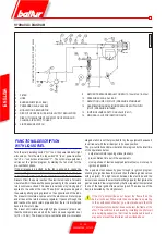
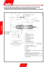
HYDRAULIC DIAGRAM
1 FILTER
2 HOSE
3 BURNER PUMP (20-22 BAR)
4 PRESSURE GAUGE 0-40 BAR
5 MODULATION SERVOMOTOR
6 DISK WITH SCREWS FOR AIR/FUEL SUPPLY REGULATION
7 DISK WITH ADJUSTMENT SCREWS FOR OPENING AND
CLOSING AIR SUPPLY TO HEAD
8 AIR PRESSURE SWITCH
9 RETURN PRESSURE REGULATOR MIN 10-12 bar MAX 18-20 bar
10 PRESSURE GAUGE 0-40 BAR
11 REDUCTION UNIT OR (PILOT) PRESSURE STABILISER
12 GAS MINIMUM AND MAXIMUM PRESSURE SWITCH WITH
(PILOT) PRESSURE INTAKES
13 IGNITION FLAME SAFETY GAS VALVE (PILOT)
14 MAIN GAS VALVE FOR IGNITION FLAME
CONNECTION
TO SUPPL
Y CIRCUIT
SEE BT
8666-3
Summary of Contents for 66875410
Page 2: ......
Page 37: ...35 42 0006080764 _201312 ITALIANO schema elettrico...
Page 38: ...36 42 0006080764 _201312 ITALIANO...
Page 39: ...37 42 0006080764 _201312 ITALIANO...
Page 40: ...38 42 0006080764 _201312 ITALIANO...
Page 41: ...39 42 0006080764 _201312 ITALIANO...
Page 42: ...40 42 0006080764 _201312 ITALIANO...
Page 43: ...41 42 0006080764 _201312 ITALIANO RAMPA PILOTA RAMPA PRINCIPALE...
Page 46: ...2 42 0006080764 _201312 ENGLISH...
Page 79: ...35 42 0006080764 _201312 ENGLISH Wiring diagram...
Page 80: ...36 42 0006080764 _201312 ENGLISH...
Page 81: ...37 42 0006080764 _201312 ENGLISH...
Page 82: ...38 42 0006080764 _201312 ENGLISH...
Page 83: ...39 42 0006080764 _201312 ENGLISH...
Page 84: ...40 42 0006080764 _201312 ENGLISH...
Page 85: ...41 42 0006080764 _201312 ENGLISH PILOT TRAIN MAIN TRAIN...
Page 87: ......


