19 / 42
0006080764 _201312
0002933420
ENGLISH
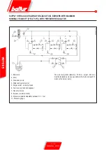
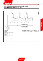
MODEL SPECIFIC GAS PILOT
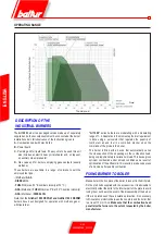
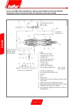
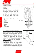
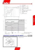
ADJUSTMENT PRINCIPLE DIAGRAM
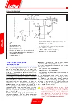
dESCRIPTION OF OPERATION
WITH METHANE
The capacity variation range that can be reached goes approximately
from 1 to 1/5 in respect to the maximum capacity rate of the
appliance.
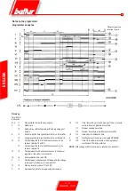
The burner is provided with a limit micro-switch that prevents the
ignition if the flow rate regulator is not at the minimum setting. In
accordance with safety standards, burner ignition is preceded by
a pre-ventilation stage of the combustion chamber. During the pre-
ventilation phase, the air and gas pressure servomotor detects the
air pressure and it reaches its maximum opening position. Therefore,
pre-ventilation is carried out with air inlet open at its maximum opening
position. From the above, the total pre-ventilation time is provided by:
air shutter opening time + pre-purge time + time for return of air
shutter to minimum position .
If sufficient pressure is detected by the ventilation air pressure
switch, the ignition transformer will cut in at the end of the ventilation
phase and later the pilot flame valves will open. Gas reaches the
combustion head, mixes with air supplied by the fan and is ignited.
Flow is regulated by the flow regulator incorporated in one of the two
ignition flame valves (pilot). After the pilot flame valves have been
enabled, the ignition transformer cuts out.
The burner is thus operating on the pilot flame alone. Flame presence
is detected by the UV photocell. At this point the programmer relay
resets lockout position and supplies power to the main valves
causing them to open. The gas flows through the main valves and
out the combustion head in the amount permitted by the “minimum”
position of the flow regulator. The main flame of the burner is now
ignited at the minimum setting.
The pilot circuit cuts out after the main valves open.
The modulator servo-motor cuts in after the main valves open, and
on a consent signal from the modulating thermostat or pressure
switch (assuming they are set at a temperature or pressure value
in excess of the temperature or pressure in the boiler), the servo-
motor will start turning to provide a gradual increase in the supply
of gas and combustion air until the maximum nominal flow at which
the burner has been set is obtained.
Gas delivery is not determined by the main valve but by the
position of the gas distribution adjustment valve (see drawing
0002933530).
The burner remains in the maximum flow position until the
temperature or pressure are high enough to trip the modulation
probe, which reverses the rotation of modulation servomotor. The
inverse rotation and therefore the air and gas supply reduction
occurs shortly thereafter. With this procedure, the modulation system
attempts to balance the amount of heat supplied to the boiler with
respect to the amount the boiler releases for use. From this point
on, the modulation probe installed on the boiler measures any
variation requests and automatically adjusts fuel and combustion
air supply, by starting the modulation servomotor and increasing or
reducing rotation as necessary. If the threshold value (temperature
or pressure), to which the complete shut-down device (thermostat
or pressure switch) is set, is reached even with minimum gas and
air output, the burner will be shut down when the device is triggered.
When temperature or pressure returns below the shut-down device
tripping value, the burner is activated once again according to the
program described previously. If a flame is not detected within
the safety time, the control equipment goes into “lockout” mode
(complete shut down of the burner and illumination of the lockout
indicator light). To “resume” the equipment operation press the
dedicated button.
Summary of Contents for 66875410
Page 2: ......
Page 37: ...35 42 0006080764 _201312 ITALIANO schema elettrico...
Page 38: ...36 42 0006080764 _201312 ITALIANO...
Page 39: ...37 42 0006080764 _201312 ITALIANO...
Page 40: ...38 42 0006080764 _201312 ITALIANO...
Page 41: ...39 42 0006080764 _201312 ITALIANO...
Page 42: ...40 42 0006080764 _201312 ITALIANO...
Page 43: ...41 42 0006080764 _201312 ITALIANO RAMPA PILOTA RAMPA PRINCIPALE...
Page 46: ...2 42 0006080764 _201312 ENGLISH...
Page 79: ...35 42 0006080764 _201312 ENGLISH Wiring diagram...
Page 80: ...36 42 0006080764 _201312 ENGLISH...
Page 81: ...37 42 0006080764 _201312 ENGLISH...
Page 82: ...38 42 0006080764 _201312 ENGLISH...
Page 83: ...39 42 0006080764 _201312 ENGLISH...
Page 84: ...40 42 0006080764 _201312 ENGLISH...
Page 85: ...41 42 0006080764 _201312 ENGLISH PILOT TRAIN MAIN TRAIN...
Page 87: ......

