background image

53 / 119

0006081062_200709

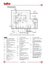
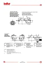
Electrical connections

The burner manufacturer’s diagram is valid for the relief valve connections.

LEGEND

For the entire catalogue sheet

Limit switch commutation 

contact for air damper OPEN 
position 

AL 

Remote signalling of lock-out 

stop (alarm) 

AR 

Main relay (operating relay) 

with “ar…” contacts

AS 

Appliance fuse 

BR 

Lock-out relay with “br…” con

-

tacts 

BV 

Fuel valve 

bv... 

Control contact for gas valve 
CLOSED position

d… 

Remote control switch or relay 

EK…  Lock-out push-button 

FE 

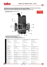
Ionization current probe 
electrode 

FR 

Flame relay with “fr…” con

-

tacts 

GP 

Gas pressure switch 

Main switch 

L1 

Fault indicator light 

L3 

Ready for operation indicator

LK 

Air damper 

LP 

Air pressure switch 

LR 

Power regulator 

Auxiliary commutation contact 

for air damper  
MIN position 

M… 

Motor fan or burner 

NTC 

NTC resistor 

QRA..  UV probe  


Thermostat or pressure probe

RV 

Fuel valve with continuous 

regulation 

Fuse 

SA 

Air damper servomotor 

SB 

Safety limiter (temperature, 

pressure, etc.) 

SM 

Programmer synchronous mo

-

tor 

In the case of servomotor: au-

xiliary contact for consensus 

for fuel valve depending on air 
damper position 

Flame signal amplifier 

Thermostat or safety pressure 

switch 

In the case of servomotor: 

limit switch commutation con

-

tact for air damper CLOSED 
position 

Ignition transformer 

ZBV 

Pilot burner fuel valve 

• 

Valid for forced draught bur-

ners, with obe tube

•• 

Valid for pilot burners with in

-

termittent operation

(1) 

Input for increasing operating 
voltage for UV probe (probe 
test) 

(2) 

Input for forced energizing of 

flame relay during functional 

test of flame supervision cir

-

cuit (contact XIV) and during 

safety time t2 (contact IV) 

3

Do not press EK for more 
than 10 seconds 

Summary of Contents for BGN 200 LX

Page 1: ...uzioni per bruciatori modello Instruction for burners model Instrucci nes para quemadores modelos Mode d emploi brule r BGN200LX LX V BGN300LX LX V BGN390LX LX V BGN540LX LX V 0006081062_200709 IT GB...

Page 2: ...dents SP Antes de empezar a usar el quemador lea detenidamente el folleto ADVERTENCIAS DIRIGIDAS AL USUARIO PARA USAR CON SEGURIDAD EL QUEMADOR que va con el manual de instruc ciones y que constituye...

Page 3: ...ntrol box 52 Irregularity cause remedy 57 Air regulation servomotor 92 MB VEF B01 Monobloc valve 94 Electric diagrams 107 ESPA OL P GINA Caracteristicas tecnicas 14 L nea de alimentaci n gas Fijaci n...

Page 4: ...olio e misti lato gasolio EN 60335 1 2003 EN 50165 1997 A1 2001 EN 55014 1 1994 e 2 1997 Organo di Sorveglianza secondo la Direttiva Gas 90 396 CEE CE0085 DVGW Statement of Conformity We hereby declar...

Page 5: ...c t fioul EN 60335 1 2003 EN 50165 1997 A1 2001 EN 55014 1 1994 e 2 1997 Organe de Surveillance selon la Directive Gaz 90 396 CEE CE0085 DVGW Declaraci n de Conformidad Declaramos bajo nuestra respons...

Page 6: ...se si dovesse traslocare e lasciare l apparecchio assicurarsi sempre che il libretto accompagni l apparecchio in modo che possa essere consultato dal nuovo proprietario e o dall installatore Per tutti...

Page 7: ...o compromettere il buon funzionamento del bruciatore Per la prima messa in funzione dell apparecchio far effettuare da personale professionalmente qualificato le seguenti verifiche a il controllo dell...

Page 8: ...equipment is sold or transferred to another owner or if the owner moves and leaves the equipment make sure that the booklet always goes with the equipment so it can be consulted by the new owner and o...

Page 9: ...by qualified technicians and in compliance with current law and regulations since incorrect installation may cause damage to person animals or things for which damage the manufacturer shall not can b...

Page 10: ...s est siempre con el aparato para que pueda ser consultado por el nuevo propietario y o instalador Para todos los aparatos con elementos opcionales o kits incluidos los el ctricos hay que utilizar sol...

Page 11: ...l aparato el personal cualificado profesionalmente tiene que controlar a la estanqueidad en el tramo interior y exterior de los tubos de abastecimiento del combustible b la regulaci n del caudal del c...

Page 12: ...appareil doit tre vendu ou transf r un autre propri taire ou si celui ci doit d m nager et laisser ce dernier toujours v rifier que la notice accompagne l appareil afin qu il puisse tre consulter par...

Page 13: ...v rifications suivantes par du personnel qualifi a le contr le de l tanch it de la partie interne et externe des tuyaux d arriv e du combustible b la r glage du d bit du combustible en fonction de la...

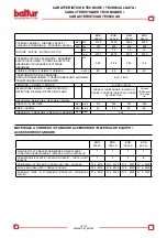
Page 14: ...LX POTENZA TERMICA THERMIC CAPACITY PUISSANCE THERMIQUE POTENCIA TERMICA MAX kW 2150 3600 3950 5900 MIN kW 250 400 400 600 MOTORE MOTOR MOTEUR MOTOR kW 3 7 5 7 5 15 r p m 2870 2870 2870 2920 POTENZA...

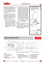
Page 15: ...le to attach it to horizontal piping after the lter The gas pressure regulator must be adjusted while working at the maximum capa city actually used by the burner The delivery pressure must be adjuste...

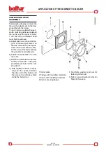
Page 16: ...e trates into the combustion cham ber the amount recommended by the generator s manufacturer b Position seal insulation 3 on the tube unit c Fasten the combustion head as sembly to the boiler 1 using...

Page 17: ...LS BGN 200 LX BGN 390 LX Plate and refractory wall hole to be drilled to 12 MEASURING THE PRESSURE IN THE COMBUSTION CHAMBER If the hole in the door is too small to allow the hose to pass and the door...

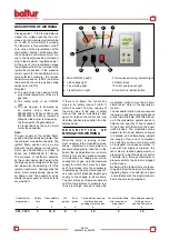
Page 18: ...rn the cam 6 so that the oat exerts suf cient pres sure on the two cables then ti ghten the screws that fasten the cable oat Finally connect the two 7 and 4 pole plugs IMPORTANT the housings for the c...

Page 19: ...ton 8 on the display panel D E S C R I P T I O N O F MODULATION WORKING When the burner is running at mini mum capacity if the modulation probe allows adjusted to a temperature or pressure value great...

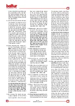
Page 20: ...ame 8 By acting on the special screw for adjusting the gas and air pressure ratio on the gas valve mod MB VEF DMV VEF set the desired value see the speci c instruc tions for the gas valve MB VEF DMV...

Page 21: ...t the air regulation servomotor sets to the minimum to perform the control also in this position 16 To set the air and thus gas regulation servomotor to the minimum the modulation switch must be press...

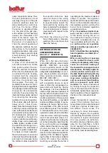
Page 22: ...d is equipped with a regulation device so as to open or close the air passage be tween disk and head By closing the passage it is thus possible to obtain a high pressure upstream of the disk also for...

Page 23: ...let Gate sensibly open Burner s head adjusting and xing knob Burner s adjustable head MAINTENANCE The burner does not need special maintenance However it is advis able to check that the gas lter is cl...

Page 24: ...distance see diagram relative to the speci c burner model NOTE if the distance X is reduced the NOx emissions value falls Always adjust the distance X between the minimum and maximum valuesspeci ed i...

Page 25: ...ut stop is triggered at the end of the to lerated post combustion period The tests will end only at the end of the pre ventilation time of the next start up The validity of working of the ame control...

Page 26: ...contact for air damper MIN position M Motor fan or burner NTC NTC resistor QRA UV probe R Thermostat or pressure probe RV Fuel valve with continuous regulation S Fuse SA Air damper servomotor SB Safe...

Page 27: ...54 119 0006081062_200709 Notes on the programmer Programmer sequence Output signals on terminal...

Page 28: ...valid for types of Series 032 since they involve si multaneous activation of cams X and VIII Working The above diagrams illustrate both the connection circuit and the sequencer mechanism control progr...

Page 29: ...nt to terminal 8 by limit switch contact a Terminals 6 7 and 15 remain powered until the defect is eliminated P Lock out stop because of lack of air pressure signal Any lack of pressure from this mome...

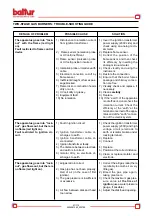
Page 30: ...as pipe has not been properly bled of air in the case of rst ignition 3 The gas pressure is insuf cient or excessive 4 Air ow between disk and head too narrow SOLUTION 1 Invert the ignition transforme...

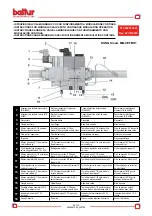
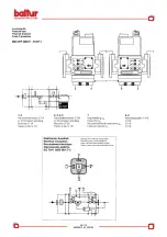
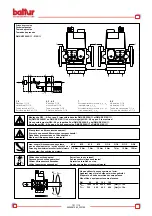
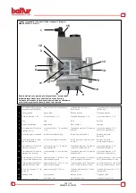
Page 31: ...bile da 0 75 1 a 3 1 Setting screw ratio V Tornillo de regulaci n para la relaci n del valor Vis de r glage du rapport V 10 Attacco misuratore G 1 8 possible sui due lati prima della V1 Test point con...

Page 32: ...uesta a tierra conforme a las normas locales Tomas de presi n 1 3 4 6 Tap n con tornillo G 1 8 2 Toma para medir la presi n 5 Tap n con tornillo M4 7 8 9 Rosca interna G 1 8 para los tubos medici n im...

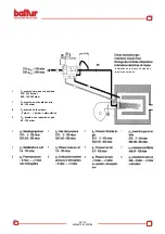
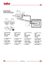
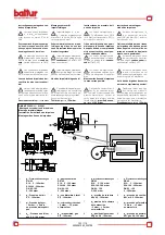
Page 33: ...s de medici n impulsos de presi n 1 Pe presi n del gas en la entrada S10 5 100 mbar S30 100 360 mbar 7 PL presi n en el soplador aire 0 4 100 mbar 8 PF presi n en la caldera 2 mbar 5 mbar o atmosf ric...

Page 34: ...11 5125 11 N 0006080717 Rev 2002 06 ISTRUZIONI VALVOLA ELETTROMAGNETICA DOPPIA CON FUNZIONAMENTO A MODULAZIONE CONTINUA INSTRUCTIONS FOR DOUBLE SOLENOID VALVE gAS AIR RATIO CONTROL INSTRUCTIONS ELECTR...

Page 35: ...98 119 0006081062_200709...

Page 36: ...99 119 0006081062_200709...

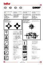
Page 37: ...i o 500 mbar DN65 S10 pe min 5mbar pe max 100mbar DN65 S30 pe min 100mbar pe max 360mbar DN80 125 pe min 5mbar pe max 360mbar V1 V2 Classe A Groupe 2 V1 V2 klasse A groep 2 V1 V2 Categor a A grupo 2 V...

Page 38: ...eld Debe haber preconectado un filtro adecuado Monte um filtro apropriado a montante Montage de GW A5 sur pos 2 impossible dans les DMV SE 5080 11 et DMV SE 5100 11 Bij DMV SE 5080 11 en DMV SE 5100 1...

Page 39: ...o el ctrico do press stato DIN 43 650 Flange de entrada Liga o de press o G 1 4 Perneira Logotipo Liga o de press o G 1 8 Press o do ventilador pL Parafuso de ajuste Rela o V Parafuso de ajuste Ajuste...

Page 40: ...las l neas y las l neas de impul sos comprobar la estanqueidad a presi n atmosf rica Utilizar el spray detector de fugas s lo de forma dirigida presi n de ensa yo pm x 100 mbar Instru es de montagem L...

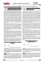
Page 41: ...la correzione riduzione dell erogazione di gas agendo sui relativi dispositivi di cui la valvola provvista Ilgrupporegolazione pressionevienepre tarato in fabbrica I valori di taratura devono essere p...

Page 42: ...as de la instalaci n en el lugar de trabajo Alojamiento para la llave hexa gonal hueca de 2 5 mm TARAGE DU GROUPE DE R GLAGE PRESSION La vanne modulation mod MB VEF B01 op re en augmentant automatique...

Page 43: ...0 75 1 V pBr pL Nullpunkorrektur 1 mbar Zero point adjustement 1 mbar Correction point z ro 1 mbar Correzione punto zero 1 mbar MB VEF Einstellbereich Setting range Plange de r glage Campo di regolazi...

Page 44: ...107 119 0006081062_200709 SCHEMA ELETTRICO WIRING DIAGRAM ELECTRIC DIAGRAM...

Page 45: ...108 119 0006081062_200709 SCHEMA ELETTRICO WIRING DIAGRAM ELECTRIC DIAGRAM...

Page 46: ...109 119 0006081062_200709 SCHEMA ELETTRICO WIRING DIAGRAM ELECTRIC DIAGRAM...

Page 47: ...110 119 0006081062_200709 SCHEMA ELETTRICO WIRING DIAGRAM ELECTRIC DIAGRAM...

Page 48: ...111 119 0006081062_200709 SCHEMA ELETTRICO WIRING DIAGRAM ELECTRIC DIAGRAM...

Page 49: ...112 119 0006081062_200709 SCHEMA ELETTRICO WIRING DIAGRAM ELECTRIC DIAGRAM...

Page 50: ...113 119 0006081062_200709 SCHEMA ELETTRICO WIRING DIAGRAM ELECTRIC DIAGRAM...

Page 51: ...114 119 0006081062_200709 SCHEMA ELETTRICO WIRING DIAGRAM ELECTRIC DIAGRAM...

Page 52: ...115 119 0006081062_200709 SCHEMA ELETTRICO WIRING DIAGRAM ELECTRIC DIAGRAM...

Page 53: ...116 119 0006081062_200709 SCHEMA ELETTRICO WIRING DIAGRAM ELECTRIC DIAGRAM...

Page 54: ...117 119 0006081062_200709 SCHEMA ELETTRICO WIRING DIAGRAM ELECTRIC DIAGRAM...

Page 55: ...118 119 0006081062_200709 SCHEMA ELETTRICO WIRING DIAGRAM ELECTRIC DIAGRAM...

Page 56: ...119 119 0006081062_200709 SCHEMA ELETTRICO WIRING DIAGRAM ELECTRIC DIAGRAM...

Page 57: ...La Casa por lo tanto se reserva cualquier posibilitad de modificati n de datos t cnicos y otras anotaciones Ce manuel rev t caract re purement indicatif La maison se reserve la possibilit de modifier...

Reviews: