10 / 22
98318_201204
00
02
90
06
01
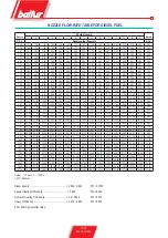
pressure of 16 bar using diesel fuel. Bear also in mind that as the
burner is working with only the first flame activated, the first
nozzle fuel supply corresponds to the values indicated on the
10 bar table since the first flame pressure regulator is set to
this value. It is of course possible to vary within wide limits
the ratio between the first and the second flames by replacing
the nozzles. However, bear in mind that, in order to achieve a
proper operation, fuel supply using the first flame should not
be lower than the minimum capacity (indicated on the rating
plate) for the burner. A lower capacity could make ignition
difficult and the combustion obtained with the first flame alone
might not be optimal.
As the flame is present inside the combustion chamber,
the burner is controlled and monitored by the photocell and
thermostats. The programmer continues its travel and deactivates
the ignition transformer. The burner is lit working at full rate.
If the program is interrupted (due to a power supply failure, manual
action or the intervention of the thermostat, etc.) during the pre-
wash stage, the programmer returns to its starting position and
automatically repeats the entire burner ignition sequence.
When the temperature or the pressure reaches that set by the
thermostat or pressure switch, the burner stops.
The equipment resumes operation automatically as the temperature
or pressure value has reduced its value by the necessary amount.
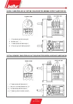
1 - Valve usually open
2 - Valve usually open
3 - Return
4 - Suction
5 - Foot valve
6 - Pump (16 bar)
7 - 1
st
flame pressure regulator (10 bar)
8 - Adjusting screw
9 - Air adjustment servomotor
10 - 2
nd
flame valve (13 bar)
11 - 1
st
flame valve (7 bar)
12 - 2
nd
flame nozzles
13 - 1
st
flame nozzle
If, during operation the flame is lacking for any reason, the photocell
activates immediately (one second) and stops the relay supply and
turns it off. Therefore, the washing solenoid valve deactivates and
quickly bleeds out the existent pressure and the diesel fuel atomised
spray is intercepted by the automatic closing of the atomiser unit
valve as soon as the pressure drops below 7 bar.
In this case, the ignition sequence is automatically repeated and,
if the flame re-ignites as usual, the burner starts working again as
usual, if not (irregular flame or fails to light completely) the equipment
goes automatically into lock-out.
EQUIPMENT FEATURES
Equipment and
relative programmer
Safety time
in seconds
Pre-ventilation
and pre-wash time
in seconds
Post-ignition
in seconds
Time between 1
st
and 2
nd
flame
in seconds
LAL 1.25
Cyclic relay
5
22.5
15
7.5
HYDRAULIC DIAGRAM


