background image

11 / 22

98318_201204

FIRST FILLING UP OF PIPELINES

After making sure that the protective plastic caps inside the pump 

fittings have been removed, proceed as follows:

1)  Move the switch placed on the burner to the “0” position. This 

operation prevents the burner from activating automatically. 

2)  Make sure, in case of a three-phase burner, that the motor 

revolves anti-clockwise when you are watching it from the pump 

side.  The rotation direction can be determined also watching 

the rotation direction of the fan through the inspection window 

on the back of the scroll.   To start the motor, close the remote 

control switch manually (pressing on the mobile part) for a 

few seconds and watch the rotation direction of the fan.   If it 

is necessary to reverse the rotation direction, reverse the two 

phases on the line input terminals (L1 - L2 - L3).

Note: 

To positively determine the rotation direction, wait until the 

fan turns very slowly because it is quite easy to misinterpret 

the rotation direction.

3)  Disconnect  the  flexible  pipes,  if  they  have  already  been 

connected, from both suction and return piping.

4)  Immerse the end of the suction flexible pipe into a vessel 

containing either lubricating oil or fuel oil (do not use low 

viscosity  products  such  as  diesel  fuel,  petrol,  gasoline, 

kerosene. etc.).

5)  Now press on the mobile part of the motor remote control switch 

to start up the motor and the pump. Wait until the pump has 

drawn 1 or 2 cups of lubricant, then stop. This will prevent the 

pump from running dry and will increase the suction power.

Note: 

Pumps operating at 2800 r.p.m. must not work dry otherwise 

they will seize in a very short time.

6)  Now connect the flexible pipes to the suction line and open 

all the gate valves fitted on this line and any other similar fuel 

cut-off device.

7)  Now press on the mobile part of the motor remote control 

switch to start up the pump that extracts the fuel from the tank.  

When you see the fuel coming out of the return line (not yet 

connected), stop.

Note:  

If the piping is long, it may be necessary to bleed the air out 

through the cap; if the pump is not fitted with a cap, remove 

the cap from the pressure gauge.

8)  Connect the return flexible pipe to the return line and open the 

valves fitted on this pipe.  Now the burner is ready for ignition.

IGNITION AND ADJUSTMENT

Before igniting the burner make sure:

a)  The  feeding  line  connections  to  thermostats  or  pressure 

switches are made exactly according to electric diagram of the 

appliance.

b)  There is fuel in the tank and water in the boiler.
c)  All the gate valves fitted on the diesel oil suction and return 

pipes should be open; the same thing applies to any other fuel 

cut-off device.

d)  The exhaust of combustion products takes place freely (boiler 

and chimney gate valves open).

e)  Make sure that the burner head penetrates into the combustion 

chamber according to the instructions of the boiler manufacturer. 

The burner is equipped with a coupling flange to the boiler, 

which slides on the burner head.

f)  The nozzles fitted on the burner should be suitable for the boiler 

capacity; replace them with others, if necessary. Under no 

circumstances should the delivered quantity of fuel exceed the 

maximum amount required by the boiler and the max. amount 

permitted for the burner. Bear in mind that the combustion head 

has been designed for nozzles with a 45° spray angle.

Note: 

To obtain a proper ignition and combustion using the first flame 

alone, the fuel supply should not be considerably lower than the 

minimum capacity (indicated on the plate) for the specific burner.

Note: 

The burner has a switch to pass manually from the 1

st

 to the 

2

nd

 stage.

To ignite the burner proceed as follows:

1)  Disconnect the thermostat (if connected) to prevent second 

flame activation.

2)  Slightly open the air regulator (0002904000 / 0002904010) and 

let in an amount of air deemed necessary for burner operation 

with the 1

st

 flame and lock it in this position; set the air control 

device in an intermediate position on the combustion head (see 

chapter “Adjusting the air on the combustion head”).

3)  Turn on the main switch and the equipment main switch.
4)  The programmer activates and performs the pre-set program, 

activating the devices of which the burner consists. The burner 

ignites as described in chapter “Operation description”.

5)  When the burner is operating with the 1

st

 flame, adjust the 

amount of air necessary to ensure an efficient combustion 

(0002904000 / 0002904010). It is better if the amount of air 

for the 1

st

 flame is slightly reduced in order to ensure a perfect 

ignition even in the most critical conditions.

6)  After adjusting the air for the 1

st

 flame the burner stops, cutting 

off the voltage to the main switch. The terminals of the 2

nd

 flame 

thermostat terminal board connect and the first and second 

stage switch moves to the second stage position.

7)  Adjust the combustion air for the second flame (0002904000 / 

0002904010)

8)  The equipment activates again, it starts and automatically 

switches to the 2

nd

 flame established by the programmer 

according to the pre-set program.

9)  With  the  equipment  operating  with  the  2

nd

  flame,  adjust 

(0002904000 / 0002904010) the amount of air necessary to 

ensure efficient combustion with the airflow necessary to ensure 

good combustion. Subsequently check combustion with the 

special instruments. In the absence of proper instrumentation 

use flame colour as a guide. We recommend that the adjustment 

is performed so as to obtain a soft light orange flame; avoid 

red flames with smoke and white flames with an exaggerated 

excess of air. The air regulator should be in a position to allow a 

percentage of carbon dioxide (CO

2

) in the smoke, varying from 

Summary of Contents for BT 350 DSG

Page 1: ...BT 350 DSG ISTRUZIONI ORIGINALI IT 98318_201204 Manual user instructions TWO STAGE DIESEL BURNER ...

Page 2: ......

Page 3: ...TBML Comist GI GI Mist Minicomist PYR RiNOx Spark Sparkgas TBG TBL TBML TS IBR IB Variant LX for low NOx emissions Description forced air burners of liquid gaseous and mixed fuels for residential and industrial use meet the minimum requirements of the European Directives 2009 142 CE D A G 2004 108 CE C E M 2006 95 CE D B T 2006 42 CE D M and conform to European Standards UNI EN 676 2008 gas and co...

Page 4: ... the owner moves and leaves the equipment make sure that the booklet always goes with the equipment so it can be consulted by the new owner and or installer For all equipment with optionals or kits including electrical only origi nal accessories must be used WARNING NOTES FOR THE USER HOW TO USE THE BURNER SAFELY BURNERS This equipment must be used only for its expressly stated use applied to boil...

Page 5: ... and regulations since incorrect installation may cause damage to person animals or things for which damage the manufacturer shall not can be held responsible Before installation it is advisable to carry out careful internal cleaning of all tubing for the fuel feed system to remove any residues that could jeopardise the proper working of the burner For first start up of the equipment have qualifie...

Page 6: ...OLTAGE 3N 400 V 50 Hz STANDARD ACCESSORIES BT 350 DSG BURNER COUPLING FLANGE No 1 INSULATING GASKET No 2 STUD BOLTS No 4 M20 HEXAGONAL NUTS No 4 M20 FLAT WASHERS N 4 M 20 FLEXIBLE PIPES No 2 1 L 1500 FILTER 1 1 Combustion head 2 Insulating gasket 3 Burner coupling flange 4 Combustion head adjustment knob 5 Solenoid valves 6 Air adjustment servomotor 7 Electrical panel 8 Fan motor 9 photocell 10 Pu...

Page 7: ...5 22 98318_201204 OPERATING RANGE MOD OVERALL DIMENSIONS G A1 A2 B C D E Ø FØ E I1 L M H BT 350 DSG 1050 525 525 920 1960 350 560 360 275 440 440 400 540 M 20 365 ...

Page 8: ...erent spray angle will not cause any problems flame separation disk or combustion head fouling violent ignition etc 6 When removing the protective plastic cap from the nozzle seat be careful because if the sealing surface is indented a light scoring would be enough it will cause fuel dripping 7 Make sure that the burner head enters the combustion chamber according to the boiler manufacturer s inst...

Page 9: ...up slope towards the burner to prevent possible formation of gas bubbles Where several burners are installed in one boiler room it is essential for every burner to have its own suction pipe Only return pipes can lead to a single manifold pipe with an adequate cross section leading to the tank Never connect the return pipe directly to the suction pipe It is a good practice to properly heat insulate...

Page 10: ...turn pipe 8 Automatic fuel interception device at burner shut off 9 One way valve 10 Foot valve SUCTION FEED SYSTEM H Height difference between minimum fuel tank level and pump axis L Total length of pipeline including vertical length Subtract 0 25 mt for every bend or gate valve NOTE Comply with the regulations in force for any components missing in the pipelines PUMP AXIS PUMP AXIS PUMP AXIS H m...

Page 11: ...y ducts increases When the diesel pressure reaches 7 bar it opens the mechanical valve located in the atomiser unit Therefore the diesel reaches the first flame nozzle and and from this it enters into the combustion chamber finely atomised The pressure stabilises at a value of approx 10 bar since the first flame pressure regulator is adjusted to this value The atomised diesel comes out of the nozz...

Page 12: ...e entire burner ignition sequence When the temperature or the pressure reaches that set by the thermostat or pressure switch the burner stops The equipment resumes operation automatically as the temperature or pressure value has reduced its value by the necessary amount 1 Valve usually open 2 Valve usually open 3 Return 4 Suction 5 Foot valve 6 Pump 16 bar 7 1st flame pressure regulator 10 bar 8 A...

Page 13: ...ce freely boiler and chimney gate valves open e Make sure that the burner head penetrates into the combustion chamberaccordingtotheinstructionsoftheboilermanufacturer The burner is equipped with a coupling flange to the boiler which slides on the burner head f The nozzles fitted on the burner should be suitable for the boiler capacity replace them with others if necessary Under no circumstances sh...

Page 14: ...lator backwards degree by degree until reaching the position in which the ignition is regular and accept this new position as definitive We remind you that for the first flame is preferable to limit the quantity of air to the strictly lowest amount possible needed for safe ignition even in the most difficult circumstances CHECKS After starting up the burner check the safety devices photocell block...

Page 15: ...device of the 2nd flame pressure switch or thermostat re activates the total fuel and air delivery rate If the burner operates only with the 1st flame it will stop completely when the pressure or the temperature reaches the tripping point set on the control device pressure switch or thermostat The burner starts up automatically again when the pressure or temperature falls below the limit to which ...

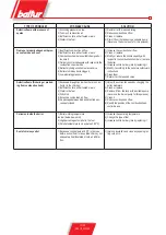
Page 16: ...low 4 Rectify the position of the combustion head control device 5 Clean or replace it The burner goes into lock out without spraying fuel Red lamp on 1 One phase missing 2 Inefficient electric motor 3 Diesel fuel not reaching the pump 4 No diesel fuel in the tank 5 Gate valve on the suction pipe closed 6 Nozzle clogged 7 Motor three phase rotates in the wrong direction see arrow 8 Bottom valve le...

Page 17: ...according to the boiler manufacturer s instructions 6 Clean them 7 Return it at the required value Defective flame flickering or protrud ing from combustion head 1 Excessive draught only when there is an ex tractor in the chimney 2 Inefficient nozzle either fouled or worn 3 Water in the fuel 4 Dirty disk 5 Excessive combustion air flow 6 Air passage between disk and blast tube ex cessively closed ...

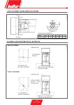
Page 18: ...NCIPLE OF AIR CONTROL WRONG ADJUSTMENT Combustion head Air passageway wide open Knobs for controlling and fastening the combustion head Air combustion inlet gate valve mostly closed Knobs for controlling and fastening the combustion head CORRECT ADJUSTMENT Air combustion inlet gate valve sensibly open Combustion head Air flow quite locked C a u t i o n Av o i d complete closure ...

Page 19: ...ection Return Pump plate Delivery nozzle 1 4 Pressure gauge connection Heating element seat Pump pressure pre setting 20 22 bar Suction 1 4 vacuum gauge connection Return Delivery nozzle 1 4 Pressuregaugeconnection Heating element seat Pump pressure pre setting 20 22 bar Pump plate ...

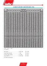
Page 20: ... 50 11 13 11 90 12 62 13 30 13 95 14 57 15 17 15 74 16 29 16 83 17 34 17 85 18 34 18 81 19 28 3 50 4 00 12 72 13 60 14 42 15 20 15 94 16 65 17 33 17 99 18 62 19 23 19 82 20 40 20 95 21 50 22 03 4 00 4 50 14 31 15 30 16 22 17 10 17 94 18 73 19 50 20 24 20 95 21 63 22 30 22 95 23 57 24 19 24 78 4 50 5 00 15 90 17 00 18 03 19 00 19 93 20 82 21 67 22 48 23 27 24 04 24 78 25 49 26 19 26 87 27 54 5 00 5...

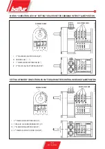
Page 21: ...nd FLAME VALVE ACTUATING CAM 40 REFERENCE INDEX ADJUSTABLE CAMS I 2nd FLAME AIR ADJUSTING CAM 60 II TOTAL AIR CLOSURE BURNER OFF 0 III 1st FLAME AIR ADJUSTING CAM 20 IV 2nd FLAME VALVE ACTUATING CAM 40 MOTOR CONECTRON LKS 160 SETTING FOR AIR SHUTTER COMMAND IN FIRST FLAME POSITION SETTING OF MOTOR CONECTRON LKS 160 FOR AIR SHUTTER CONTROL IN SECOND FLAME POSITION ...

Page 22: ...20 22 98318_201204 WIRING DIAGRAM ...

Page 23: ...21 22 98318_201204 ...

Page 24: ...ento Fe Italy Tel 39 051 6843711 Fax 39 051 6857527 28 www baltur it info baltur it The information contained in this catalogue is not binding The manufacturer reserves the right to change the technical data and any other data it contains ...

Reviews: