44
REGULATION OF THE COMBUSTION HEAD AND FLAME DISK
The burner is equipped with a combustion head
which can be regulated (by moving it backwards
or forwards) in such a way as to close more or
open more the air passage between the disk and
the head. By throttling the passage, it is possible
to achieve high pressure upstream the disk, and
therefore high velocity and air turbulence for low
inputs as well. High velocity and air turbulence
ensure better penetration in the fuel and are
therefore an optimum mixture and allow the burner
to operate with good flame stability.
High air pressure, upstream the disk, might be
necessary in order to avoid flame pulsations, and
it is considered practically indispensable when the
burner is operating with a pressurized furnace and/
or high thermal load.
It is evident from above, that the position of the
device which regulates the air on the combustion
head should be put in such a position as to always
obtain a decidedly high air pressure value behind
the disk. It is advisable to regulate in such a way
as to achieve a throttling of the air between the
disk and the head; this will necessitate a
considerable opening of the air shutter which
regulates the flow to the burner’s fan suction.
Obviously these adjustments should be carried out
when the burner is operating at maximum delivery
desired. In practice, commence regulating with the
combustion head in an intermediate position, start
up the burner and make a first adjustment as
previously described.
When maximum delivery desired has been
reached, proceed with correcting the position of
the combustion head; move it backwards and
forwards in such a way as to obtain an air flow
suitable for the fuel delivery with the air regulation
in suction considerably open. If the combustion head is pushed forwards (which causes a reduction in the air
passage between the head and the disk), avoid closing it completely.
When regulating the combustion head, proceed with centering it perfectly with respect to the disk.
It must be pointed out that, if perfect centering with respect to the disk is not obtained, bad combustion and
excessive heating of the head could occur which would result in its rapid deterioration.
A control can be carried out by looking through the spy holes situated on the back of the burner; then tighten
home the screws that lock the combustion head in position. The distance between the disk and the nozzle,
regulated by the manufacturer, must be reduced only if the atomized fuel cone coming out of the nozzle wets the
disk and fouls it up.
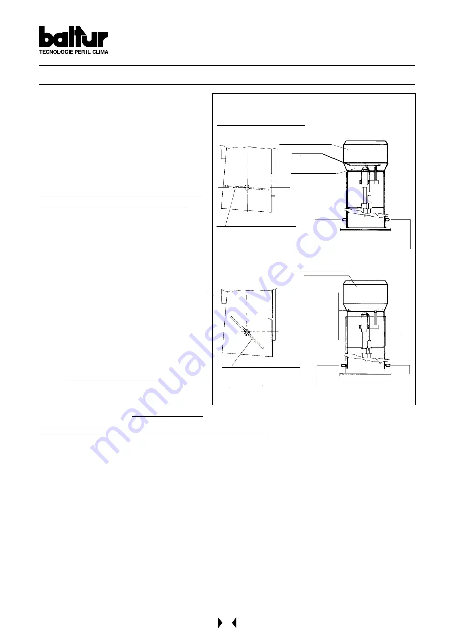
GENERAL DIAGRAM AIR REGULATION
N° BT 8608/1
INCORRECT REGULATION
CORRECT REGULATION
Combustion head
Flame disk
Air flow large
opening
Control and fixing knobs
of combustion head
Combustion air inlet with very
locked shutter
Combustion head
Combustion air inlet with very
opened shutter
Control and fixing knobs
of combustion head
Air flow quite
locked.
ATTENTION:
Avoid complete
locking.
Summary of Contents for BT 75 DSPN /D
Page 25: ...25 APPARECCHIATURA DI COMANDO E CONTROLLO LAL N 7153 Rev 07 1996...
Page 26: ...26 N 7153 Rev 07 1996 APPARECCHIATURA DI COMANDO E CONTROLLO LAL...
Page 27: ...27 N 7153 Rev 07 1996 APPARECCHIATURA DI COMANDO E CONTROLLO LAL...
Page 28: ...28 N 7153 Rev 07 1996 APPARECCHIATURA DI COMANDO E CONTROLLO LAL...
Page 29: ...29 N 7153 Rev 07 1996 APPARECCHIATURA DI COMANDO E CONTROLLO LAL...
Page 30: ...30 N 7153 Rev 07 1996 APPARECCHIATURA DI COMANDO E CONTROLLO LAL...
Page 31: ...31 N 7153 Rev 07 1996 APPARECCHIATURA DI COMANDO E CONTROLLO LAL...
Page 32: ...32 N 7153 Rev 07 1996 APPARECCHIATURA DI COMANDO E CONTROLLO LAL...
Page 49: ...49 N 7153 Rev 04 1996 INSTRUCTIONS LAL CONTROL BOX...
Page 50: ...50 N 7153 Rev 04 1996 INSTRUCTIONS LAL CONTROL BOX...
Page 51: ...51 N 7153 Rev 04 1996 INSTRUCTIONS LAL CONTROL BOX...
Page 52: ...52 N 7153 Rev 04 1996 INSTRUCTIONS LAL CONTROL BOX...
Page 53: ...53 N 7153 Rev 04 1996 INSTRUCTIONS LAL CONTROL BOX...
Page 54: ...54 N 7153 Rev 04 1996 INSTRUCTIONS LAL CONTROL BOX...
Page 55: ...55 N 7153 Rev 04 1996 INSTRUCTIONS LAL CONTROL BOX...
Page 56: ...56 N 7153 Rev 04 1996 INSTRUCTIONS LAL CONTROL BOX...
Page 73: ...73...
Page 74: ...74...
Page 75: ...75...
Page 76: ...76...
Page 77: ...77...
Page 78: ...78...
Page 79: ...79...
Page 80: ...80...
Page 81: ...81...
Page 82: ...82...
Page 83: ...83...
Page 84: ...84...
Page 86: ......
Page 87: ......
Page 88: ......
Page 89: ......
Page 90: ......
Page 91: ......
Page 92: ......
Page 93: ......
Page 94: ......
Page 95: ......


