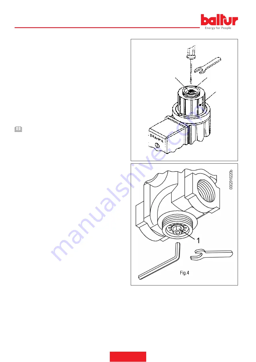
INSTRUCTIONS FOR THE ADJUSTMENT OF SOLENOID
VALVES EG 12*L ... AND E 6G*
Flow rate adjustment
To vary the gas flow rate to the burner, adjust block 3 of the time delay
device shown in Fig. 4.
Slacken the cover lock screw (only slacken the screw without paint
seal) and rotate the entire unit.
Turning it clockwise decreases the flow rate and inversely the flow
rate increases.
Maximum adjustment is determined by the regulator screw stop and
a thrust ring, which are both fitted inside the sheath.
Solenoid valve opening time adjustment:
It can be obtained using the adjustment screw 1 indicated in fig. 4.
Turning it clockwise, the screw tends to block the oil passage
hole, obtaining a long valve opening time. By turning it instead
anticlockwise, the opening time decreases as the screw frees the
area where the oil flows.
CAUTION / WARNINGS
The adjustment screw 1 is supplied correctly calibrated by the
manufacturer and, therefore, must not be re-adjusted.
Regulation of the initial flow rate rapid release:
This is done by rotating regulator 2 shown in fig. 4.
Turning it with a 6 mm hexagonal wrench in a clockwise direction
decreases the rapid release, turning it anticlockwise increases it.
INSTRUCTIONS FOR THE REGULATION OF THE SOLENOID
VALVE EG12*AR-EG 12*SR
Flow rate regulation:
To be able to vary the gas flow rate, use regulator A and an 8-mm
hex wrench
Or a 4 mm countersunk hexagon wrench.
Turning clockwise, the flow rate decreases. Turning anticlockwise,
the flow rate increases.
2
1
3
0002910220
Fig. 4
2
22 / 30
0006080749_202206
ENGLISH
Summary of Contents for BTG 3,6
Page 2: ......
Page 31: ...SCHEMI ELETTRICI 29 30 0006080749_202206 ITALIANO...
Page 61: ...WIRING DIAGRAMS 29 30 0006080749_202206 ENGLISH...
Page 63: ......


