10 / 36
0006080095_201207
ENGLISH
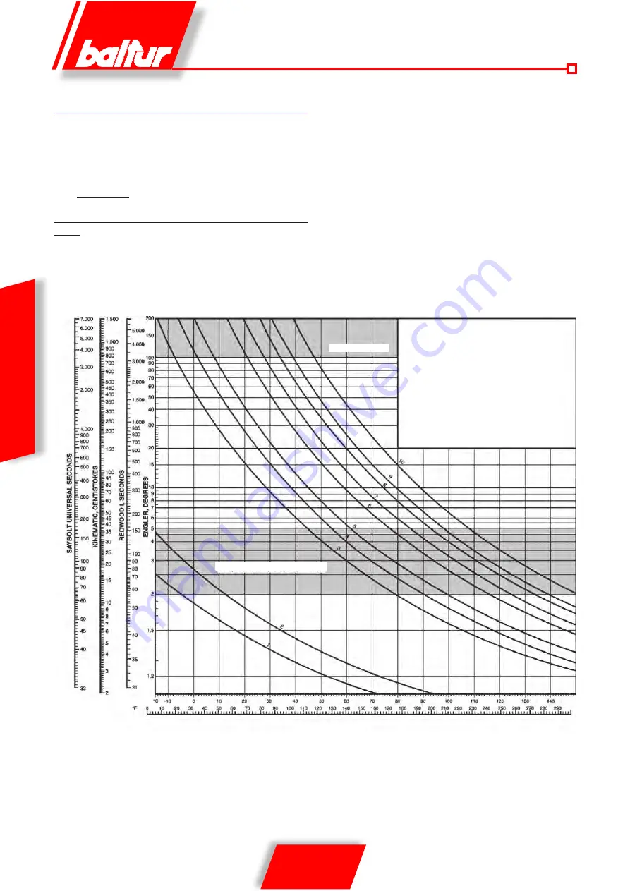
Viscosity diagram - temperature
FUEL SUPPLY SYSTEM
The burner pump must receive fuel from a suitable supply circuit,
including an auxiliary pump with pressure adjustable from 0,5 to
2 bar.
The supply pressure value of the fuel at the burner pump (0,5 ÷
5 bar) must not vary either when the burner is not in operation or
when it is operating at the maximum level fuel supply called for by
the boiler.
The supply circuit must be built according to our drawings n°
8666/3 Pipe dimensions depend on their length and the capacity of
the pump being used.
Our instructions only regard what is necessary for ensuring good
operation.
The regulations to be observed in order to comply with antismog
laws as well as the local Firemen’s’ regulations, should be referred
to in the relevant publications.The attached tables show diagrams
of the different types of systems depending on the position of the
tank with respect to the burner.
The maximum amount of vacuum that the pump can withstand
when operating regularly and silently is 35 cm. of Hg ; if this limit is
exceeded, normal pump operations can no longer be guaranteed.
Maximum suction and return pressure = 1 bar.
VISCOSITY
TEMPERATURES
Viscosity range for atomization
Pumping limit
Curve 1 Diesel
"
2 Extrafluid
"
3 Fluid 3/5
"
4 Fluid 5/7
"
5 thick 8
"
6 Thick 15 - 20
"
7 Thick, viscosity
24 at 50°C
"
8 Thick, viscosity
35 at 50°C
"
9 Thick, viscosity
50 at 50°C
" 10 Thick, viscosity
85 at 50°C
Summary of Contents for COMIST 180
Page 2: ......
Page 36: ...34 36 0006080095_201207 ITALIANO SCHEMA ELETTRICO...
Page 38: ...36 36 0006080095_201207 ITALIANO...
Page 72: ...34 36 0006080095_201207 ENGLISH WIRING DIAGRAM...
Page 74: ...36 36 0006080095_201207 ENGLISH...
Page 108: ...34 36 0006080095_201207 ESPA OL ESQUEMA ELECTRICO...
Page 110: ...36 36 0006080095_201207 ESPA OL...
Page 144: ...34 36 0006080095_201207 FRAN AIS SCH MA LECTRIQUE...
Page 146: ...36 36 0006080095_201207 FRAN AIS...
Page 147: ......


