42
ENGLISH
1)
Feeding circuit pressure regulator (adjusting range between 0,5 and 3 bar with pressure gauge 0 ÷ 4 bar)
2)
Air/gas purge valve, normally closed, open slightly only in case of gas purge
3)
Hot oil recovery and degassing tank diameter = 200 mm. height = 530 mm. It must be installed at a level at
least 0.5 meters higher then the pumps
4)
Water and system drain
5)
Burner pump filter with resistance and thermostat
6)
Burner pump ( 20 ÷ 22 bar pressure)
7)
Pressure gauge (0 ÷ 40 bar)
8)
Manually controled by-pass to exclude steam preheater when this is cold (open to exclude the steam
preheater)
9)
Condensate flow indicator
10)
Steam trap
11)
Steam filter
12)
Steam pressure gauge (0 ÷ 10 bars)
13)
1/2” steam pressure reducer adjustable from 1 to 8 bars
14)
Steam cut off gate valve
15)
Steam preheaters
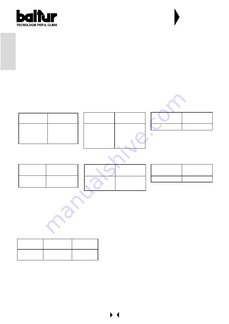
Model
TS 0 - 1
TS 2
TS 3
TS 4
N° Steam
preheaters
1
2
3
4
Model
PYR 2 - 3 - 4
PYR 5 - 6
PYR 7
PYR 8
PYR 9 - 10
N° Steam
preheaters
1
2
3
4
5
Model
GI 1000
N° Steam
preheaters
3
16)
Maximum oil pressure pressostat (adjust at 28 bar) on request
17)
Electric preheaters
Model
TS 0 - 1 - 2
TS 3 - 4
N° Electric
preheaters
1
2
Model
PYR 2-3- -5
PYR 6-7-8
PYR 9-10
N° Electric
preheaters
1
2
3
Model
GI 1000
N° Electric
preheaters
2
18)
Self-cleaning filter
19)
Thermometer and thermostat probe
20)
Preheater safety valve (adjusted at 30 bar)
21)
Atomizing unit with nozzle
22)
Gas pilot burner
23)
Pilot gas train safety valves with flow regulator (open completely only for PYR)
24)
Pilot gas train minimum and maximum gas pressure switch
25)
TRU Nozzle return thermostat
26)
Return pressure regulator ( see nozzle diagram and table)
Model
TS
PYR
Minimum
pressure
10 ÷ 12 bar
4 ÷ 6 bar
Maximum
pressure
20 ÷ 22 bar
20 ÷ 22 bar
27)
Modulation servomotor
28)
Air/fuel regulation comand disk
29)
Air shutters
30)
Air pressure switch
31)
Normally closed By-pass
32)
Non return valve
A)
Steam inlet min. 12 bar
B)
Air exhaust
C)
Steam trap
N° 0002901000
N° 1 di 2
PRINCIPLE DIAGRAM FOR HEAVY OIL TS-
PYR-GI 1000 MAIN PUSHING SYSTEM
(DEGASSING-FILTERING-PUSHING AND HEATING)
Summary of Contents for GI 1000 DSPN-D
Page 23: ...23 ITALIANO SCHEMA DI PRINCIPIO REGOLAZIONE ARIA PER MODELLO GI 1000 DSPN D N 0002933410...
Page 24: ...24 ITALIANO SCHEMA DI PRINCIPIO REGOLAZIONE PILOTA GAS PER MODELLO GI 1000 DSPN D N 0002933930...
Page 50: ...50 ENGLISH BURNER GI 1000 DSPN D AIR FEEDING ADJUSTMENT PRINCIPLA DIAGRAM N 0002933410...
Page 51: ...51 ENGLISH N 0002933930 BURNER GI 1000 DSPN D GAS PILOT ADJUSTMENT PRINCIPLE DIAGRAM...
Page 67: ......
Page 68: ......
Page 69: ......
Page 70: ......
Page 71: ......
Page 72: ......
Page 73: ......
Page 74: ......
Page 75: ......


