38
ENGLISH
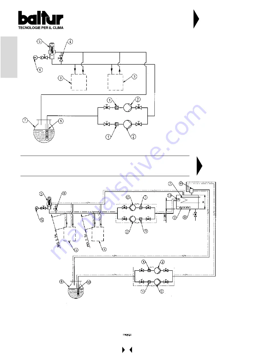
HYDRAULIC DIAGRAM TO THE BURNERS GI 1000-TS-
PYR SERIES OPERATING WITH LIGHT OIL OR HEAVY
OIL WITH MAX NOMINAL VISCOSITY 5 °E AT 50 °C
N° BT 8868/2
1 - Filter
2 - Circulation pumps (one spare)
3 - Burner pushing central station
4 - By pass (normally closed)
5 - Pressure regulator adjustable from 0,5
to 2 bar
6 - Pressure gauge (0 ÷ 4 bar)
7 - Main tank
8 - Oil heating at steam or at hot water in
order to keep, also during a short period
of non operation, a temperature value
sufficient for the flow in the piping
N° BT 8866/4
HYDRAULIC DIAGRAM FOR BURNERS GI 1000 - TS - PYR SERIES
OPERATING WITH HEAVY OIL (50°E AT 50°C) WITH AUXILIARY HEATER
1
- Filter
2
- Circulation pumps (one spare)
3
- Starter resistance with thermostat
4
- Burner pushing central unit
5
- Pressure regulator (from 0,5 to 3 bar)
6
- By pass (normally closed)
7
- Steam or hot water coil to heat oil
8
- Auxiliary heater
9
- Main tank
10
- Steam orhot water heating to keep the oil at a
temperature at which it can flow through the pipes,
even while the machine is down
11
- Degasifier (Ø = 100 - H = 300)
12
- Pressure gauge (0 ÷ 4 bar)
13
- Thermometer
Electric heating wires
Summary of Contents for GI 1000 DSPN
Page 23: ...23 ITALIANO SCHEMA DI PRINCIPIO REGOLAZIONE ARIA PER MODELLO GI 1000 DSPN D N 0002933410 ...
Page 50: ...50 ENGLISH BURNER GI 1000 DSPN D AIR FEEDING ADJUSTMENT PRINCIPLA DIAGRAM N 0002933410 ...
Page 51: ...51 ENGLISH N 0002933930 BURNER GI 1000 DSPN D GAS PILOT ADJUSTMENT PRINCIPLE DIAGRAM ...
Page 67: ......
Page 68: ......
Page 69: ......
Page 70: ......
Page 71: ......
Page 72: ......
Page 73: ......
Page 74: ......
Page 75: ......


