ENGLISH
12 / 40
0006080098_201803
LIQUID FUEL SUPPLY SYSTEM
The burner pump must receive the fuel from a suitable supply circuit
featuring an auxiliary pump which may feature a pressure regulator
adjustable from 0.5 to 3 bar.
The maximum amount of vacuum that the pump can withstand when
operating regularly and silently is 35 cm Hg. If this limit is exceeded,
normal pump operation can no longer be guaranteed.
The fuel supply pressure to the burner pump must not change both
with burner off and with working burner at the maximum fuel output
required by the boiler.
The supply circuit can be realized without pressure regulator, using
the dedicated hydraulic diagram.
The pipe dimensioning must be carried out according to the pipe
length and the flow rate of the installed pump.
To ensure an efficient operation, it is necessary to install suction and
return pipes with welded fittings and to avoid the use of threaded
connections, which often cause air infiltration interfering with the
pump correct operation.
For systems requiring pipes with a relatively small diameter we
recommend the use of copper pipe
For unavoidable connections, use biconic fittings.
Where a removable coupling is required, use the welded flange
method inserting a fuel resistant gasket to obtain a positive sealing.
Do not connect the return pipe directly to the suction pipe.
Only return pipes can lead to a single manifold pipe with a suitable
cross section leading to the fuel tank.
The suction pipe should run up-slope towards the burner to avoid
possible formation of gas bubbles.
Where more burners are installed in one boiler room, it is essential
that every burner has its own suction pipe.
Heat-insulate the suction and return pipes to prevent hazardous fuel
cooling.
These instructions ensure a good operation of the product.
The anti-pollution prescriptions, as well as the provisions set forth by
the local authorities, refer to the specific publications in force in the
country where the product will be installed.
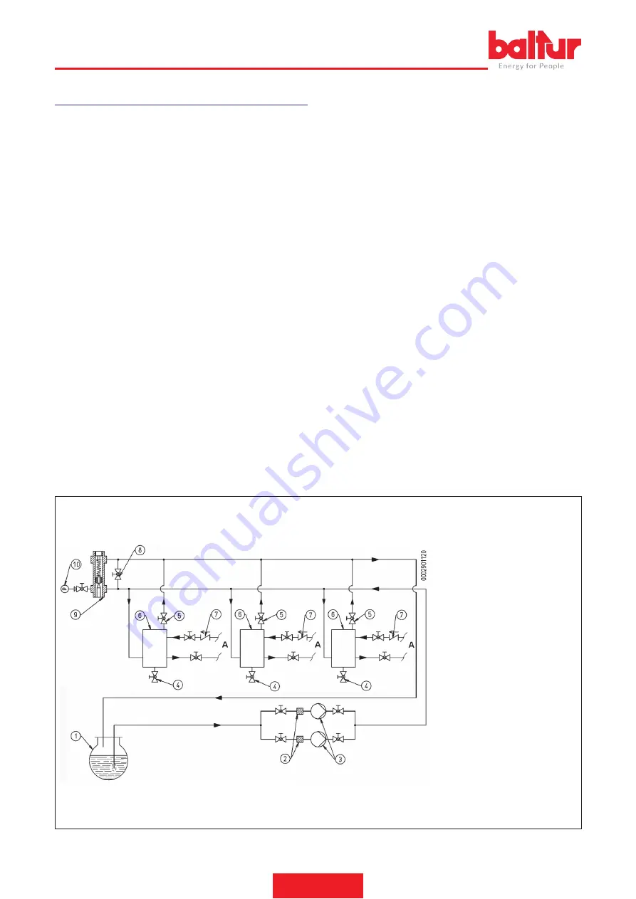
HYDRAULIC DRAWING OF PRESSURE SUPPLY FOR ONE OR MORE TWO-STAGE OR MODULATING BURNERS WITH MAXIMUM
NOMINAL VISCOSITY (5° E AT 50° C) WITH PRESSURE REGULATOR
The fuel recovery tanks (diameter ~ 150
mm - height ~ 400 mm) must be installed
as close as possible to the burner at 0.5
m above the burner pump.
1
Main tank
2
Liquid fuel filter
3
Circulation pumps
4
Water and system outlet
5
Air-gas drain normally closed
6
Fuel recovery and degasifier
Summary of Contents for GI 350 DSPG
Page 2: ......
Page 39: ...ITALIANO 37 40 0006080098_201803 SCHEMI ELETTRICI...
Page 40: ...ITALIANO 38 40 0006080098_201803...
Page 41: ...ITALIANO 39 40 0006080098_201803...
Page 79: ...ENGLISH 37 40 0006080098_201803 WIRING DIAGRAMS...
Page 80: ...ENGLISH 38 40 0006080098_201803...
Page 81: ...ENGLISH 39 40 0006080098_201803...
Page 83: ......


