background image

83 / 84


0006080766

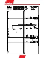
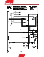
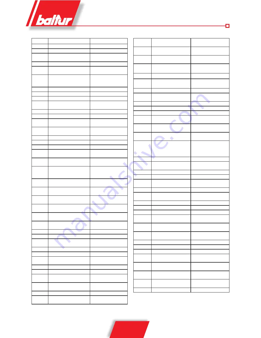
SIGLA

IT

GB

A1

APPARECCHIATURA

CONTROL BOX

A2

TERMOSTATO ELETRONICO

ELECTRONIC THERMOSTAT 

A3

CONTROLLO TENUTA VAL-

VOLE

VALVES TIGHTNESS 

CONTROL 

B1

FOTOCELLULA UV

UV PHOTOCELL

B2

TERMORESISTENZA PT100

THERMORESISTANCE 

PT100

DW

PRESSOSTATO CONTROLLO 

TENUTA VALVOLE

PRESSURE SWITCH 

FOR VALVE TIGHTNESS 

CONTROL

F1

RELE’ TERMICO

THERMAL RELAY 

F2

RELE’ TERMICO POMPA  

PUMP THERMAL RELAY 

FU1÷4

FUSIBILI

FUSES

HO

LAMPADA FUNZIONAMENTO 

RESISTENZE AUSILIARIE

AUXILIARY RESISTANCES 

LAMP 

H1

SPIA DI FUNZIONAMENTO  

OPERATION LIGHT  

H10

SPIA FUNZIONAMENTO OLIO   OIL SIGNAL LAMP 

H11

SPIA FUNZIONAMENTO GAS  

NATURAL GAS SIGNAL 

LAMP 

H12

LAMPADA CARICAMENTO 

SERBATOIO  

TANK LOADING LAMP 

H2

SPIA DI BLOCCO 

LOCK-OUT SIGNAL LAMP  

H3

SPIA DI BLOCCO LDU11  

 LDU11 BLOCK LAMP 

H4.1 / 4,2

SPIA RESISTENZE  

RESISTANCES LAMP  

H5

LAMPADA FUNZIONAMENTO 

AUTOMATICO

AUTOMATIC LAMP OPE-

RATION

H6

LAMPADA FUNZIONAMENTO 

MANUALE

MANUAL LAMP OPERATION

H7

LAMPADA BLOCCO RELE' TER-

MICO MOTORE VENTOLA

FAN MOTOR THERMAL 

SWITCH RELAY BLOCK 

LAMP

H8

LAMPADA BLOCCO TERMICO 

MOTORE POMPA

LAMP PUMP MOTOR THER-

MAL STOP

H9

LAMPADA TENSIONE QUADRO 

ELETTRICO

CONTROL PANEL VOLTAGE 

LAMP

K2

CONTATTORE MOTORE 

POMPA  

PUMP MOTOR CONTACTOR 

K3

RELE’ AUSILIARIO MOTORINO 

CICLICO  

AUXILIARY RELAY CICLIC 

MOTOR 

K4

CONTATTORE CAMBIO COM-

BUSTIBILE 

CONTACTOR OIL CHAN-

GING 

K6

RELE’ AUSILIARIO PER RESI-

STENZE

AUXILIARY RELE’ FOR 

RESISTANCES

KD

CONTATTORE TRIANGOLO 

TRIANGLE CONTACTOR 

KL

CONTATTORE DI LINEA

LINE CONTACTOR

KR1 / KR2 CONTATTORE RESISTENZE

RESISTANCES CONTAC-

TOR

KT

TEMPORIZZATORE

TIMER

KY

CONTATTORE DI STELLA

 STAR CONTACTOR

M

MOTORINO CICLICO CON 

CONTATTI M1-M2-M3

CYCLIC MOTOR WITH M1-

M2-M3 CONTACTS

MP

MOTORE POMPA

PUMP MOTOR

MV

MOTORE

MOTOR

N1

REGOLATORE ELETTRONICO  REGULATEUR ELECTRO-

NIQUE 

P M

PRESSOSTATO DI MASSIMA 

GAS MAX. PRESSURE 

SWITCH 

PA

PRESSOSTATO ARIA  

 AIR PRESSURE SWITCH 

Pm

PRESSOSTATO DI MINIMA 

GAS MIN. PRESSURE 

SWITCH 

PmP

PRESSOSTATO DI MINIMA 

RAMPA PILOTA

PILOT TRAIN MINIMUM 

PRESSURE SWITCH

PMP.

PRESSOSTATO DI MASSIMA 

RAMPA PILOTA

PILOT TRAIN MAXIMUM 

PRESSURE SWITCH

Q1

SEZIONATORE GENERALE 

BLOCCO PORTA

MAIN DOOR LOCK SWITCH

RP.RF.RG

RESISTENZE 

POMPA,FILTRO,GRUPPO 

GROUP,FILTER,PUMP 

RESISTANCES 

RS1/RS2

RESISTENZE

RESISTANCES

S1

INTERRUTTORE MARCIA 

ARRESTO

ON-OFF SWITCH

S2

PULSANTE SBLOCCO

RE-SET PUSH BUTTON

S3

PULSANTE SBLOCCO LDU11 LDU11 RE-SET PUSH 

BUTTON

S4

SELETTORE AUT-MAN

AUT-MAN SELECTOR

S5

COMMUTATORE MIN-MAX

MIN-MAX COMMUTATOR

S6

SELETTORE GAS-OLIO

GAS-OIL SELECTOR

S7

PULSANTE CARICAMENTO 

SERBATOIO

TANK LOADING SWITCH

S10

PULSANTE A FUNGO DI 

EMERGENZA

EMERGENCY MUSHROOM-

HEAD BUTTON

SFG

MICRO FINE CORSA SER-

RANDA GAS

GAS GATE MICRO LIMIT 

SWITCH

SO 

COMANDO CAMBIO 

COMBUSTIBILE  A DI-

STANZA (APERTO=GAS, 

CHIUSO=OLIO)

REMOTE FUEL CHANGE 

AUTOMATIC  CON-

TROL (OPEN=GAS, 

CLOSE=HEAVYOIL)

T2

TERMOSTATO 2 STADIO 

 2ND STAGE THERMOSTAT 

TA

TRASFORMATORE D'ACCEN-

SIONE

IGNITION TRANSFORMER

TC

TERMOSTATO CALDAIA 

 BOILER THERMOSTAT

Tmin

TERMOSTATO DI MINIMA 

MIN. THERMOSTAT

TRU

TERMOSTATO RITORNO 

UGELLO

NOZZLE RETURN THER-

MOSTAT 

TS

TERMOSTATO DI SICUREZZA SAFETY THERMOSTAT 

TSR1/TSR2 TERMOSTATO SICUREZZA 

RESISTENZE

RESISTANCES SAFETY 

THERMOSTAT 

U1

PONTE RADDRIZZATORE

RECTIFIER BRIDGE  

X1

MORSETTIERA BRUCIATORE  BURNER TERMINAL  

X2

MORSETTIERA BRUCIATORE BORNES DE RACCORD

X5.B, X5.S

CONNETTORE MOBILE 

RAMPA GAS PRINCIPALE

MAIN GAS TRAIN FLOATING 

PLUG

X6.B, X6.S

CONNETTORE MOBILE 

RAMPA GAS PILOTA

PILOT GAS TRAIN FLOATING 

PLUG

X7

MORSETTIERA QUADRO 

PRERISCALDAMENTO

PREHEATING PANEL TERMI-

NAL BOARD

Y M

ELETTROMAGNETE

ELECTROMAGNET

Y1/Y2

ELETTROVALVOLA

ELECTROVALVE

Y10

SERVOMOTORE ARIA  

AIR SERVOMOTOR 

YP

ELETTROVALVOLA PRINCI-

PALE 

MAIN ELECTROVALVE 

YPL

ELETTROVALVOLA GAS 

PILOTA  

PILOT ELECTROVALVE 

YS

ELETTROVALVOLA DI 

SICUREZZA  

SAFETY VALVE 

YSP

ELETTROVALVOLA DI SICU-

REZZA RAMPA PILOTA

PILOT TRAIN SAFETY SOLE-

NOID VALVE

Z1

FILTRO

 FILTER

Summary of Contents for GI MIST 1000 DSPNM-D

Page 1: ...68 02 04 Краснодар 861 203 40 90 Красноярск 391 204 63 61 Курск 4712 77 13 04 Липецк 4742 52 20 81 Магнитогорск 3519 55 03 13 Москва 495 268 04 70 Мурманск 8152 59 64 93 Набережные Челны 8552 20 53 41 Нижний Новгород 831 429 08 12 Новокузнецк 3843 20 46 81 Новосибирск 383 227 86 73 Орел 4862 44 53 42 Оренбург 3532 37 68 04 Пенза 8412 22 31 16 Пермь 342 205 81 47 Ростов на Дону 863 308 18 15 Рязань...

Page 2: ...n integral and essential part of the product The works on the burner and on the esystem have to be carried out only by competent people Read carefully the instructions before starting the burner and service it The system electric feeding must be disconnected before starting working on it If the works are not carried out correctly it is possible to cause dangerous accidents E N G L I S H ...

Page 3: ...If the equipment is sold or transferred to another owner or if the owner moves and leaves the equipment make sure that the booklet always goes with the equipment so it can be consulted by the new owner and or installer For all equipment with optionals or kits including electrical only origi nal accessories must be used BURNERS This equipment must be used only for its expressly stated use applied t...

Page 4: ...out by qualified technicians and in compliance with current law and regulations since incorrect installation may cause damage to person animals or things for which damage the manufacturer shall not can be held responsible Before installation it is advisable to carry out careful internal cleaning of all tubing for the fuel feed system to remove any residues that could jeopardise the proper working ...

Page 5: ...the modulation kit Ability to operate with any type of combustion chamber Air gas mixing at combustion head and high pressure mechani cal atomisation of fuel using nozzle Ability to obtain optimal combustion values by regulating com bustion air and combustion head Maintenance facilitated by the fact that the mixing unit and the atomisation unit can be removed without having to remove the burner fr...

Page 6: ...A1 A2 B B1 B2 B3 B4 B5 B6 C D E Ø GI mist 1000 DSPNM D 1465 800 665 1257 855 402 450 575 175 163 2350 440 480 Mod F Ø G G1 L Ø M N Ø P Q R S GI mist 1000 DSPNM D 685 DN80 Rp1 2 630 M16 495 740 1910 1575 795 N 0002670552 OVERALL DIMENSIONS ...

Page 7: ...DSPGN LIGHT OIL version DSPG HEAVY OIL rated viscosity max 50 E at 50 C version DSPN D GAS Methane HEAVY OIL rated viscosity max 5 E at 50 C version GI Mist DSPNM GAS Methane LIGHT OIL version GI Mist DSPGM Note that the GI Mist 1000 DSPGM and GI Mist 1000 DSPNM burners have been designed for operation with methane gas or with liquid fuel The GI 1000 burner is a modulating burner with a modulation...

Page 8: ...y to fit insulation protection between the iron plate and the heater that is at least 10 mm thick Check that combustion head pene trates the combustion chamber by the measure requested by the manufacturer of the boiler CONNECTING THE BURNER TO THE GAS SUP PLY PIPE After you have secured the burner to the boiler remember that the burner head must penetrate the combustion chamber to the extent presc...

Page 9: ...are used Piping must be sized as a function of both its length and the flow rate of the employed pump Our instructions regard only that which is necessary for proper operation HYDRAULIC DIAGRAM OPERATING FOR ONE OR MORE BURNERS WITH MAX NOMINAL VISCOSITY 5 E AT 50 C N 0002901180 1 Main tank 2 Filter 3 Circulation pumps 4 By pass normally closed 5 Pressure regulator adjustable from 0 5 to 2 bar 6 P...

Page 10: ...AGRAM FOR ONE OR MORE MODULATING BURNERS OPERATING WITH HEAVY OIL 50 E AT 50 C WITH AUXILIARY HEATER N 0002901200 1 Main tank 2 Steam or hot water heating oil to keep a sufficienttemperature for the slide in the pipe line also during the pause 3 Filter 4 Circulation pumps 5 Steam or hot water coil to heat oil 6 Auxiliary heater 7 resistance 8 Thermometer 9 Degasifier Ø 100 mm H 300 mm 10 By pass n...

Page 11: ...ure gauge 0 40 bar 12 Electrics pre heaters 13 MINIMUM PRE HEAT THERMOSTAT 14 PRE HEAT MAXIMUM THERMOSTAT 15 AIR GAS VENT VALVE NORMALLY CLOSED OPEN SLIGHTLY ONLY IN CASE OF GAS DISCHARGE 16 Self cleanig filter 0 3 mm 17 Pressure gauge 0 40 bar 18 THERMOSTAT PT100 AND THERMOMETER 19 PRE HEATER SAFETY VALVE SET AT 32 BAR 20 REDUCTION UNIT OR PILOT PRESSURE STABILISER 21 GAS MINIMUM AND MAXIMUM PRES...

Page 12: ...upport so that it can be positioned to avoid the above described interference Just 2 5 seconds after the ignition of the pilot flame the control box powers the magnet which via a series of lever mechanisms moves the two nozzle fuel flow delivery and return interception rods The moving of these rods causes closure of the by pass inside the atomising unit consequently the in pump pressure is brought...

Page 13: ...PUMP 20 22 BAR 3 PRESSURE GAUGE O 40 BAR 4 ATOMIZER BODY 5 RETURN NOZZLE WITHOUT PIN 6 RODS WITH CLOSING PINS 7 BY PASS HOLES 8 CLOSING SPRINGS 9 OPENING ELECTROMAGNETS 10 RETURN PRESSURE CONTROL MIN 10 12 BAR MAX 18 20 BAR 11 MODULATION SERVOMOTOR 12 AIR FUEL REGULATION CONTROL DISK 13 AIR LOCKS 14 FLEXIBLE TUBE 15 IGNITION PILOT 16 MAIN GAS VALVE FOR IGNITION FLAME WITH FLOW CON TROL PILOT FLAME...

Page 14: ...RY CIRCUIT 1 Valve body 2 Adjusting screw support plug 3 Adjusting screw stop nut 4 Adjusting screw 5 Spring centering bush N 0002932080 6 Spring 7 Shutter 8 Pressure gauge connection 9 Fuel inlet 10 Fuel outlet 1 2 5 4 3 1 Valve body 2 Adjusting screw tap 3 Pressure gauge 0 40 bar 4 To the pump return 5 From the atomizing group return ...

Page 15: ... Fuel outlet Fuel return holes Fuel inlet Fuel return N B For the nozzle to operate properly its return section must never be completely closed This is achievedby regulating when the burner is started up for the first time In practice when the nozzle is operating at the maximum flow rate the difference in pressure between the delivery pump pressure and return pressure at hte returnpressure regulat...

Page 16: ...ssure gauge endof scale approx 3bar to the on pump vacuum meter coupling seat in order to check the pressure at which fuel arrives at the burner pump Apply a pressure gauge end of scale approx 30 bar to the on pump pressure gauge coupling seat in order to check the working pressure of the pump itself Apply a pressure gauge end of scale approx 30 bar to the return pressure regulator coupling to che...

Page 17: ...es as fuel flow increases as a rough guide it should be at least 10 at minimum flow and reach an optimum of about 13 at maximum flow It is inadvisable to exceed a CO2 figure of 13 so as to prevent operation with a rather limited excess of air possibly leading to a significant increase in smoke number owing to unavoidable causes changes in atmospheric pressure small dust depo sits in the fan air du...

Page 18: ... the flow regulator valve The main flame of the burner is now ignited at the mi nimum setting The pilot circuit cuts out after the main valves open The modulator servo motor cuts in after the main valves open and on a consent signal from the modulating thermostat or pressurestat assuming they are set a temperature or pressure value in excess of the temperature or pressure in the boiler the servo m...

Page 19: ...LING AIR GAS SUPPLY 3 VALVE SEAL CONTROL DEVICE AND PRESSURE SWITCH LDU 4 MAIN GAS FLAME VALVE 5 MINIMUM GAS PRESSURE SWITCH AND MAXIMUM PILOT RAMP 6 GAS SUPPLY MODULATING CONTROL BUTTERFLY VALVE 7 GAS PRESSURE CONTROL WITH BUILT IN FILTER 8 VIBRATION PROOF JOINT 9 BALL COCK 10 GAS FILTER 11 DISC WITH ADJUSTMENT SCREWS FOR OPENING AND CLOSING AIR SUPPLY TO HEAD 12 FLAME SAFETY GAS IGNITION PILOT V...

Page 20: ...e pressure is sufficient and the pressurestat fails to respond neither the ignition transformer nor the pilot flame gas valves will operate so the burner will shut down in lockout Note that lockouts during this first ignition sequence should be considered normal since the fuel supply line will still contain air which must be purged before a stable flame can be obtained Press the reset button to re...

Page 21: ...e the pressurestat regulation value with the burner operating at minimum output until such a time as the pressurestat cuts in the burner must immediately shut down in lockout Reset the burner by pressing the reset button and return the pressure stat setting to a value that enables it to detect the air pressure created during the pre purge stage 19 The gas pressurestats minimum and maximum pressure...

Page 22: ...elocity and turbulence ensure that the air penetrates the gas more thoroughly giving an optimum fuel air mixture and a stable flame With gas burners it can be essential to have high air pressure on the diffusor inlet side if pulsation of the fla me is to be prevented especially where the burner operates in a high pressure combustion chamber or in high thermal load conditions Accordingly the head m...

Page 23: ...ening and closing The VE4000B1 valves are Class A solenoid valves normally closed They may be used as ON OFF valves in the supply trains with Natural Gas Manufactured Gas or GPL on burners or combustion plants They are provided with M I and CE Approval for EN 161 ADJUSTMENT For models VE 4000B1 see fig 1 Adjustment to the flow Remove the cover from the upper section of the coil Insert a hexagonal ...

Page 24: ...which compresses the closure return spring with the rod and plate The valve remains in the open position while the pump and magnetic valve remain powered When the unit receives the signal to close or if power supply is cut off the pump shuts down the magnetic valve opens decompressing the chamber above the piston The plate is closed both by the return spring and by gas pressure The flow rate for t...

Page 25: ...e with pressure regulator Using the valve with pressure regulator the valve s out let pressure acts as a comparative value on a membrane assisted by a spring The resistance of the spring can be adju sted an constitutes the prescribed value set pressure value The membrane acts by means of an oscillating system on a by pass ball valve between the upper chamber and the servo control If the comparativ...

Page 26: ...ndards The following LFL1 features exceed the standards offering a high level of additional safety The flame detector test and false flame test start immediately after the tolerated post combustion time If the valves remain open or do not close completely after adjustment stops a lock out stop is triggered at the end of the tolerated post combustion period The tests will end only at the end of the...

Page 27: ...ion contact for air damper MIN position M Motor fan or burner NTC NTC resistor QRA UV probe R Thermostat or pressure probe RV Fuel valve with continuous regulation S Fuse SA Air damper servomotor SB Safety limiter temperature pressure etc SM Programmer synchronous motor v In the case of servomotor auxiliary contact for consensus for fuel valve depending on air damper position V Flame signal amplif...

Page 28: ...12 t5 Time between end of t4 and consensus at power regulator or at valve on terminal 20 18 t6 Post ventilation time with M2 3 t7 Time between consensus for start up and voltage at terminal 7 start delay for fan motor M2 72 t8 Start up duration without t11 and t12 3 t9 Second safety time for burners that use pilot burners 12 t10 Time from start up to beginning of air pressure control without air d...

Page 29: ...ment Electromagnetic discharges must be checked on the application plan Control program in the event of stopping indicating position of stop As a rule in the event of any kind of stop the fuel flow is cut off immediately At the same time the programmer remains immobi le as does the switch position indicator The symbol visible on the indicator reading disk indicates the type of fault No start up be...

Page 30: ...ling operation During the second verification stage this pressure must remain constant Should it drop this means that the burner on the furnace side has a blow by fault when closing Therefore the DW pressure switch operates and the tightness control equipment prevents burner start up and stops in blocked state red pilot lamp lit If second stage verification is positive the LDU 11 equipment closes ...

Page 31: ...XI programmer cam contacts Control programme t4 5s Putting control circuit under atmospheric pressure t6 7 5s Time between start up and energizing of main AR relay t1 22 5s 1st verification stage at atmospheric pressure t3 5s Putting control circuit gas under pressure t2 27 5s 2nd verification stage at gas pressure t5 67 5s Total time of tightness control up to burner operation consent t20 22 5s R...

Page 32: ...Y1 PID control approximately 130 C In the second preheater the temperature of the fuel is increased to 130 C Configuration for two or more electric preheaters C 1 D 0 E 4 F 6 Indicative parameters SP 130 0 C t d 0 8 minutes S P L 1 100 C SP 2 110 0 C t c 10 seconds S P L h 250 C P b 6 Yh 100 SLOP 0 t i 4 minutes Hy 2 1 To all intents and purposes this configuration is suitable for most users but w...

Page 33: ...ill appear 7 Proceed as previously described in order to set value t i 4 as per table Press to confirm this value and move to t d 8 Proceed as previously described in order to set value t d 0 8 as per table Press to confirm this value and move to t c 9 Proceed as previously described in order to set value t c 10 as per table Press to confirm this value and move to Yh 10 Proceed as previously descr...

Page 34: ...E ATOMIZING GROUP AND FLAME DISK N 0002933430 1 Take out the burner cover 2 Disconnect the atomising group and head tie rods 3 Disconnect the heating element connector 4 Disconnect the ignition electrode cable 5 Unscrew the Woss coupling nut to take out the pilot tube ...

Page 35: ...7 Take out the hinge upper screw and open the burner 8 Take out the blocking screw of the atomising group 9 Take out the atomising group to dismount the nozzle 10 Take out the four fixing screws of the group holder 11 Take out the group holder and flame disks ...

Page 36: ...75 84 0006080766 ...

Page 37: ...76 84 0006080766 ...

Page 38: ...77 84 0006080766 ...

Page 39: ...78 84 0006080766 ...

Page 40: ...79 84 0006080766 ...

Page 41: ...80 84 0006080766 ...

Page 42: ...81 84 0006080766 ...

Page 43: ... GIALLO GREEN YELLOW VERT JAUNE VERDE AMA RILLO BU BLU BLUE BLEU AZUL BN BRUNO BROWN MARRON MARRÓN BK NERO BLACK NOIR NEGRO BK CONNETTORE NERO CON SOVRASTAMPA BLACK WIRE WITH INPRINT CONDUCTEUR NOIR AVEC SURIMPRES SION CONDUCTOR NEGRO CON IMPRESIÓN ...

Page 44: ...RESSOSTATO ARIA AIR PRESSURE SWITCH Pm PRESSOSTATO DI MINIMA GAS MIN PRESSURE SWITCH PmP PRESSOSTATO DI MINIMA RAMPA PILOTA PILOT TRAIN MINIMUM PRESSURE SWITCH PMP PRESSOSTATO DI MASSIMA RAMPA PILOTA PILOT TRAIN MAXIMUM PRESSURE SWITCH Q1 SEZIONATORE GENERALE BLOCCO PORTA MAIN DOOR LOCK SWITCH RP RF RG RESISTENZE POMPA FILTRO GRUPPO GROUP FILTER PUMP RESISTANCES RS1 RS2 RESISTENZE RESISTANCES S1 I...

Page 45: ...μένων και οποιονδήποτε άλλων πληροφοριών κατά την αποκλειστική του κρίση Baltur S p A По вопросам продаж и поддержки обращайтесь Архангельск 8182 63 90 72 Астана 7 7172 727 132 Белгород 4722 40 23 64 Брянск 4832 59 03 52 Владивосток 423 249 28 31 Волгоград 844 278 03 48 Вологда 8172 26 41 59 Воронеж 473 204 51 73 Екатеринбург 343 384 55 89 Иваново 4932 77 34 06 Ижевск 3412 26 03 58 Казань 843 206 ...

Reviews: