28 / 44
0006080103_201309
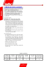
COMMAND AND CONTROL EQUIPMENT
Command and control equipment for forced air burners with
medium to high capacity (intermittent service
*) for 1 or 2 stages or modulating burners with air pressure
supervision for controlling the air gate. The command and
control equipment feature the EC mark according to the
Gas and Electromagnetic Compatibility Directive.
* For safety reasons, it is important to perform a controlled stop
each 24 hours!
As regards the standards
The following
LFL1.... features fully comply with the
Standards and ensure an extremely high safety level:
- The flame detector test and the false flame test start immediately
after the allowed post-combustion time. If the valves remain
open, or do not close immediately after the regulation stop, a
shutdown in lock condition is triggered at the end of the allowed
post-combustion time. The tests finish only at the end of the
pre-ventilation time of the next start-up.
- The operation validity of the flame control circuit is verified upon
each burner start-up.
- The fuel valve control contacts are checked for wear during the
post-ventilation time.
- One fuse integrated in the equipment protects the control
contacts against possible overloads.
As for the burner control
- The equipment allows operation with or without post-ventilation.
- A i r d a m p e r c o n t r o l l e d a c t i v a t i o n t o e n s u r e
p r e - v e n t i l a t i o n w i t h n o m i n a l a i r f l o w r a t e .
Controlled positions: CLOSED or MIN (position of ignition flame
on start-up); OPEN at the beginning and MIN at the end of the
pre-ventilation time. If the servomotors fail to position the air
damper in the preset points, the burner does not start.
- Ionization current minimum value = 6µA
- UV cell current minimum value = 70 µA
- Phase and neutral must never be inverted.
- Any place may be used for installation and assembly (IP40
protection class).
Appliance specifications
ENGLISH
Equipment
and relevant
programmer
Safety time
in seconds
Pre-ventilation time
with open gate
in seconds
Pre-ignition
in seconds
Post - ignition
in seconds
Time between 1st
flame and modulation
start in seconds
LFL 1,333
Cyclic relay
3
31.5
6
3
12
Summary of Contents for GI MIST 350 DSPGM
Page 2: ......
Page 40: ...38 44 0006080103_201309 WIRING DIAGRAM ENGLISH...
Page 41: ...39 44 0006080103_201309 ENGLISH...
Page 42: ...40 44 0006080103_201309 ENGLISH...
Page 43: ...41 44 0006080103_201309 ENGLISH...
Page 44: ...42 44 0006080103_201309 RAMPA PRINCIPALE ENGLISH...
Page 46: ...44 44 0006080103_201309 ENGLISH...
Page 84: ...38 44 0006080103_201309 ESPA OL ESQUEMA EL CTRICO...
Page 85: ...39 44 0006080103_201309 ESPA OL...
Page 86: ...40 44 0006080103_201309 ESPA OL...
Page 87: ...41 44 0006080103_201309 ESPA OL...
Page 88: ...42 44 0006080103_201309 ESPA OL RAMPA PRINCIPALE...
Page 90: ...44 44 0006080103_201309 ESPA OL...
Page 128: ...38 44 0006080103_201309 FRAN AIS SCH MA LECTRIQUE...
Page 129: ...39 44 0006080103_201309 FRAN AIS...
Page 130: ...40 44 0006080103_201309 FRAN AIS...
Page 131: ...41 44 0006080103_201309 FRAN AIS...
Page 132: ...42 44 0006080103_201309 FRAN AIS RAMPA PRINCIPALE...
Page 134: ...44 44 0006080103_201309 FRAN AIS...
Page 135: ......


