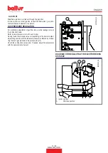
BURNER CONNECTION TO THE BOILER
For burner handling, use certified chains or ropes suitable for the bur
-
ner weight using the anchoring points (21).
HEAD UNIT ASSEMBLY
The combustion head is packaged separately from the body of the
burner.
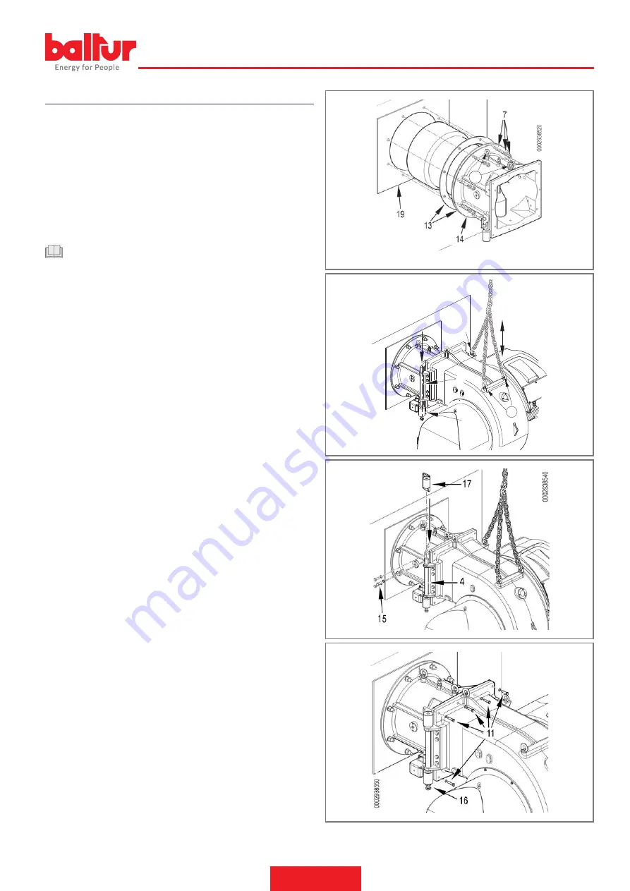
Anchor the head unit to the boiler door as follows:
•
Position the insulating seals on the sleeve (13).
•
Anchor the flange of the head unit (15) to the boiler (1) with the
stud bolts, washers and nuts provided (7)
CAUTION / WARNINGS
Completely seal the space between the burner sleeve and the
hole in the refractory material inside the boiler door with suitable
material.
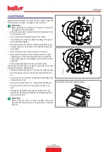
ASSEMBLY OF VENTILATION SYSTEM
Use the specific chains or ropes connected to the respective eyebolts
and slots (21) of the burner.
•
The burner has an ambidextrous hinge opening for easy access
to the combustion head with fitted burner.
•
To enable the maximum opening and so facilitate maintenance
operations, it is recommended to install the hinge pin on the side
opposite to the position where the gas train is installed.
•
To move the ventilating body, hook the specific chains or ropes
(32) to the eyebolts.
For a correct installation of the ventilating body, follow the procedure
described below:
•
Position the hinge pin (4) on the burner scroll aligned with the
lower half of the hinge (12), and insert it in the hole.
21
32
4
12
21
21
0002938530
11 / 28
0006160509_202301
ENGLISH
Summary of Contents for TBG 1600 LX ME
Page 2: ......
Page 25: ...SCHEMI ELETTRICI 23 28 0006160509_202301 ITALIANO...
Page 26: ...24 28 0006160509_202301 ITALIANO...
Page 27: ...25 28 0006160509_202301 ITALIANO...
Page 28: ...26 28 0006160509_202301 ITALIANO...
Page 29: ...27 28 0006160509_202301 ITALIANO...
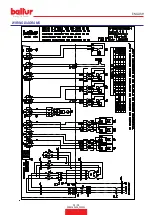
Page 53: ...WIRING DIAGRAMS 23 28 0006160509_202301 ENGLISH...
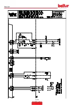
Page 54: ...24 28 0006160509_202301 ENGLISH...
Page 55: ...25 28 0006160509_202301 ENGLISH...
Page 56: ...26 28 0006160509_202301 ENGLISH...
Page 57: ...27 28 0006160509_202301 ENGLISH...
Page 59: ......


