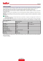
ASSEMBLING THE GAS TRAIN
The EN 676 approved gas train is sold separately from the burner.
The burner is supplied with the gas train connection facing downward.
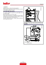
The gas train can be assembled in different ways: (11), (12) .
DANGER / ATTENTION
Install a manual shut-off valve and a vibration-proof joint
upstream of the gas valve according to the layout shown in the
block diagram.
SUPPLY LINE
B
M
M
A
B
000291
1280
12
11
10
6
4
2
3
1
9
5
8
7
15
14
13
11
16
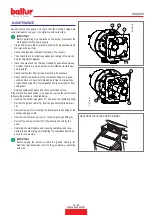
1
Air regulation servomotor
2
Air pressure switch
3
Maximum gas pressure switch
4
Gas supply control butterfly valve
5
Operating gas valve with pressure regulator
6
Valve tightness control device (integrated in the apparatus)
7
Safety valve
8
Minimum gas pressure switch and gas leak control
9
Gas filter
10
Air vibration-proof joint (not supplied)
11
Manual shut-off valve (not supplied)
12
Gas regulation servomotor
13
Ignition pilot solenoid valve
14
Gas pilot safety solenoid valve
15
Pilot train minimum pressure switch
16
Pressure regulator with built-in filter
A
TO BE SUPPLIED BY INSTALLER
B
BALTUR SUPPLY LIMIT
12 / 28
0006160509_202301
ENGLISH
Summary of Contents for TBG 1600 LX ME
Page 2: ......
Page 25: ...SCHEMI ELETTRICI 23 28 0006160509_202301 ITALIANO...
Page 26: ...24 28 0006160509_202301 ITALIANO...
Page 27: ...25 28 0006160509_202301 ITALIANO...
Page 28: ...26 28 0006160509_202301 ITALIANO...
Page 29: ...27 28 0006160509_202301 ITALIANO...
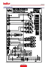
Page 53: ...WIRING DIAGRAMS 23 28 0006160509_202301 ENGLISH...
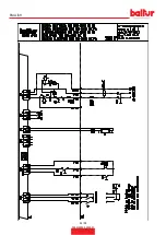
Page 54: ...24 28 0006160509_202301 ENGLISH...
Page 55: ...25 28 0006160509_202301 ENGLISH...
Page 56: ...26 28 0006160509_202301 ENGLISH...
Page 57: ...27 28 0006160509_202301 ENGLISH...
Page 59: ......


