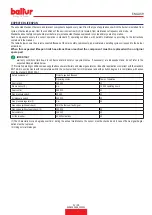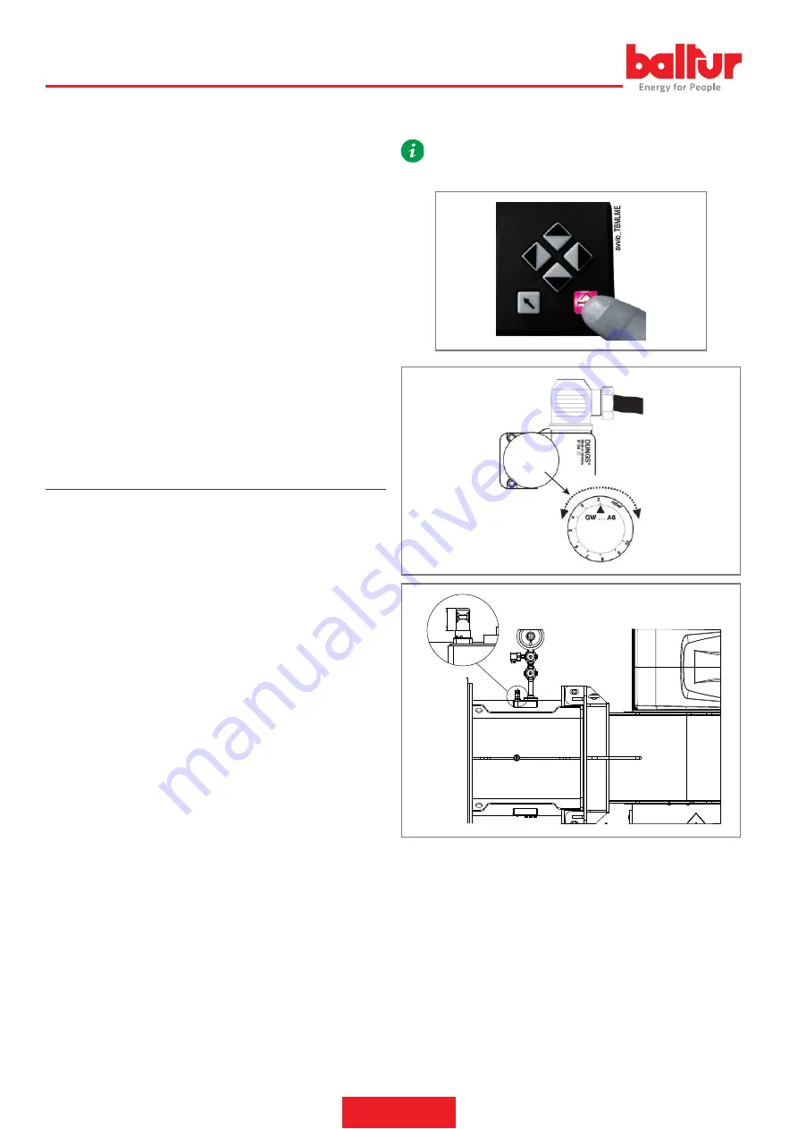
To unblock the burner, press the special pushbutton and return the
pressure switch regulator to a sufficient value in order to measure the
air pressure existing during the pre-ventilation phase.
Adjust the setting of the pressure switch to a level slightly below the
actual air pressure detected in first stage operation. Release the bur
-
ner and check that it starts up correctly.
The gas pressure control switches (minimum and maximum) prevent
the burner from operating when gas pressure does not lie between the
expected range.
The minimum value pressure switch makes use of the NO (normally
open) contact which is closed when the pressure switch detects a pres
-
sure higher than its own setting.
The maximum pressure switch uses the NC (normally closed) contact
that is closed when the pressure switch detects a pressure lower than
the value it is set to.
Adjustment of minimum and/or maximum pressure values on the pres
-
sure switches must be performed when testing the burner, on the basis
of the pressure measured in each case.
The triggering (opening of the circuit) of any of the pressure switches
when the burner is running (flame on) locks out the burner immediately.
When first switching on the burner it is essential to check that they
work properly.
FLAME SENSOR
Flame presence is detected by the dedicated control device (UV pho
-
tocell).
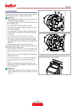
Verify the flame detector operation as follows:
•
remove the flame sensor;
•
start the burner;
•
the equipment will complete the control cycle and after two se
-
conds will lock out the burner due to the lack of ignition flame;
•
switch off the burner;
•
reposition the photocell;
•
This test should also be conducted with the burner already on;
when extracting the photocell from its seat, the apparatus should
shut down immediately.
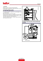
regulate the pressure switch for minimum pressure at the minimum
value of the scale, regulate the pressure switch for the maximum value
at the maximum value of the scale.
REGULATION AFTER THE BURNER CALIBRATION:
With the burner running at maximum power, regulate the pressure swi
-
tch for minimum pressure by increasing the regulation value until the
burner shuts down, read the value on the regulation ring nut and set it
to a value diminished by 20 %.
With the burner running at maximum power, regulate the pressure swi
-
tch for maximum pressure, diminishing the regulation value until the
NC (normally closed) contact opens. Read the value on the regulation
ring nut and set it to a value increased by 20 %.
The pressure switches are connected so that the triggering (opening of
the circuit) of any of the pressure switches when the burner is running
(flame on), locks out the burner immediately.
The minimum value pressure switch stops the burner that remains on
standby until the pressure is restored within the values required for
operation.
After that, the burner re-starts in an autonomous way following the igni
-
tion sequence.
•
Check the efficiency of the thermostats or boiler pressure swi
-
tches (they should shut down the burner when triggered).
IMPORTANT
In case only one pressure switch is installed on the gas train, it
must be a pressure switch for minimum pressure.
35
0002951240N5
16 / 28
0006160509_202301
ENGLISH
Summary of Contents for TBG 1600 LX ME
Page 2: ......
Page 25: ...SCHEMI ELETTRICI 23 28 0006160509_202301 ITALIANO...
Page 26: ...24 28 0006160509_202301 ITALIANO...
Page 27: ...25 28 0006160509_202301 ITALIANO...
Page 28: ...26 28 0006160509_202301 ITALIANO...
Page 29: ...27 28 0006160509_202301 ITALIANO...
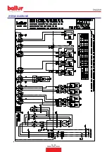
Page 53: ...WIRING DIAGRAMS 23 28 0006160509_202301 ENGLISH...
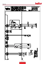
Page 54: ...24 28 0006160509_202301 ENGLISH...
Page 55: ...25 28 0006160509_202301 ENGLISH...
Page 56: ...26 28 0006160509_202301 ENGLISH...
Page 57: ...27 28 0006160509_202301 ENGLISH...
Page 59: ......


