GAS PILOT
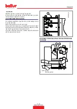
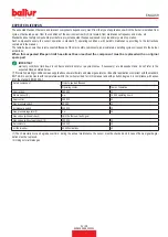
Main flame ignition is carried out through the gas pilot.
In order to allow a correct ignition, respect the flame disk - gas pilot -
nozzle distances indicated in the picture.
GAS PRESSURE REGULATION
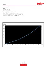
For preliminary adjustment of gas flow rate, use the leakage curve at
the combustion head.
Refer to power-pressure curve for each model.
Having found the pressure value corresponding to the desired output,
adjust the gas valve until the indicated pressure is obtained by measu
-
ring the main gas pressure at the pressure tap (13).
Check the combustion values and, if needed, adjust the parameters
with the appropriate instrument.
13
67570010_01
DIAGRAM FOR REGULATING THE ELECTRODE DISK
DISTANCE
2 ÷ 4 mm
67570010_06
1
A
38
1 - Ignition electrode
A
Pilot tube position
17 / 28
0006160509_202301
ENGLISH
Summary of Contents for TBG 1600 LX ME
Page 2: ......
Page 25: ...SCHEMI ELETTRICI 23 28 0006160509_202301 ITALIANO...
Page 26: ...24 28 0006160509_202301 ITALIANO...
Page 27: ...25 28 0006160509_202301 ITALIANO...
Page 28: ...26 28 0006160509_202301 ITALIANO...
Page 29: ...27 28 0006160509_202301 ITALIANO...
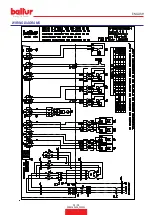
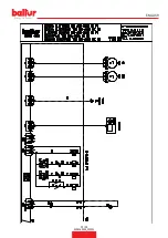
Page 53: ...WIRING DIAGRAMS 23 28 0006160509_202301 ENGLISH...
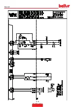
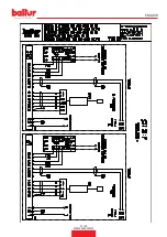
Page 54: ...24 28 0006160509_202301 ENGLISH...
Page 55: ...25 28 0006160509_202301 ENGLISH...
Page 56: ...26 28 0006160509_202301 ENGLISH...
Page 57: ...27 28 0006160509_202301 ENGLISH...
Page 59: ......


