9 / 22
0006081533_201403
ENGLISH
ELECTRICAL CONNECTIONS
The three-phase power supply line must have a
switch with fuses. The regulations further require a
switch on the burner’s power supply line, outside
the boiler room and in an easily reachable position.
For the electrical connections (line and thermostats), follow the
attached wiring diagram. To carry out the connection of the burner
to the power supply line proceed as follows:
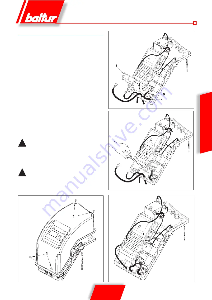
- Loosen the 4 screws (1). Remove the lid to access the burner's
electrical panel.
- Loosen screws (2) to remove the cable clamp plate (3),
pass the equipment supply cable and the modulation control
cable through the corresponding holes. Connect the motor
supply cables (4) to the radio control switch, fix the earth cable
(5) and tighten the cable gland. In case of single-phase burner,
only the L (phase) and N (neutral) cables that correspond to
L1 and L3 positions should be connected to the remote control
switch.
- Reposition the cable clamp plate.
Turn the cam (4) so that the plate exerts sufficient pressure on
the two cables, then tighten the screws that fasten the plate.
Connect the equipment supply cable and the modulation
control cable.
!
The housings for the cables are provided respectively
for cable Ø 9.5-10 mm and Ø 8.5-9 mm, this ensures the
protection rating is IP 44 (Standard IEC EN 60529) for
the electrical panel.
- To close the electrical panel lid, tighten the 4 screws (1) with
adequate torque to ensure the correct seal.
!
only professionally qualified personnel may open the
burner electrical panel.
Fig. 1
Fig. 2
Fig. 4
Fig. 3
Summary of Contents for TBG 45 ME
Page 2: ......
Page 20: ...18 22 0006081533_201403 ENGLISH WIRING DIAGRAM TBG 45 ME 60 ME ...
Page 21: ...19 22 0006081533_201403 ENGLISH MINIMUM IONISATION CURRENT 1 4 µA ...
Page 24: ...22 22 0006081533_201403 ...
Page 42: ...18 22 0006081533_201403 ESPAÑOL DIAGRAMA ELÉCTRICO TBG 45 ME 60 ME ...
Page 43: ...19 22 0006081533_201403 ESPAÑOL CORRIENTE MÍNIMA DE IONIZACIÓN 1 4 µA ...
Page 46: ...22 22 0006081533_201403 ...
Page 64: ...18 22 0006081533_201403 FRANÇAIS SCHEMA ELECTRIQUE TBG 45 ME 60 ME ...
Page 65: ...19 22 0006081533_201403 FRANÇAIS COURANT D IONISATION MINIMUM 1 4 µA ...
Page 68: ...22 22 0006081533_201403 ...
Page 86: ...18 22 0006081533_201403 TÜRKÇE ELEKTRİK ŞEMASI TBG 45 ME 60 ME ...
Page 87: ...19 22 0006081533_201403 TÜRKÇE MİNİMUM İYONİZASYON AKIMI 1 4 µA ...
Page 90: ...22 22 0006081533_201403 ...
Page 108: ...18 22 0006081533_201403 PYCCKИИ ЭЛЕКТРИЧЕСКАЯ СХЕМА TBG 45 ME 60 ME ...
Page 109: ...19 22 0006081533_201403 PYCCKИИ МИНИМАЛЬНЫЙ ТОК ИОНИЗАЦИИ 1 4 µA ...
Page 112: ...22 22 0006081533_201403 ...
Page 130: ...18 22 0006081533_201403 中 文 电气连接 TBG 45 ME 60 ME ...
Page 131: ...19 22 0006081533_201403 中 文 最小电离电流是1 4µA ...
Page 132: ...20 22 0006081533_201403 中 文 水温 压力电极 继电器控制输入 控制输入 0 4 20mA 外部温 度探头 燃气温 度探头 可能 控制输入 0 10 V ...
Page 134: ...22 22 0006081533_201403 ...
Page 135: ......


