Fig. 4
Fig. 3
Fig. 2
Fig. 1
9 / 26
0006081483_201512
ENGLISH
Fig. 4
ELECTRICAL CONNECTIONS
The monophase power supply line must have a switch with fuses.
For the electrical connections (line and thermostats), follow the at-
tached wiring diagram. To carry out the connection of the burner to
the power supply line proceed as follows:
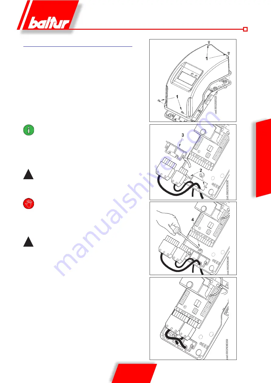
- Unscrew the 4 screws (1) in figure 1.
Remove the lid to access the burner's electrical panel.
- Loosen screws (2) to remove the cable float plate (3),
pass the two 7 and 4 pole plugs through the hole in figure 2.
- Reposition the cable float plate as in figure 3.
Turn the cam (4) so that the float exerts sufficient pressure on
the two cables, then tighten the screws that fasten the cable
float. Finally, connect the two 7 and 4 pole plugs (see figure 4).
The housings for the cables for the 7 and 4
pole plugs are for Ø 9.5-10 mm and Ø 8.5-9
mm cable respectively, this is to ensure the
protection rating of IP 44 (Standard IEC EN
60529) for the electrical panel.
- To reclose the electrical panel lid, tighten the 4 screws (1) with
adequate torque to ensure the correct seal.
!
Only professionally qualified technicians may
open the burner electrical panel.
Before performing maintenance works
disconnect the power supply and make
sure it cannot be re-connected by accident.
The inverter remains hot for a few minutes,
resulting in risk of skin burns or injuries.
!
The inverter can still be charged with high
voltage, even when disconnected from the
mains power.
Before performing any installation work on the equipment, wait five
minutes after deactivating it.
Fig. 3
Fig. 2
Fig. 1
Summary of Contents for TBG 45 PN-V
Page 2: ......
Page 28: ...26 26 0006081483_201512 ITALIANO...
Page 52: ...24 26 0006081483_201512 ENGLISH WIRING DIAGRAM...
Page 54: ...26 26 0006081483_201512 ENGLISH...
Page 55: ......


