background image

ENGLISH

7 / 35

0006081444_201610

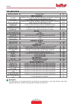
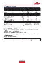
STANDARD ACCESSORIES

MODEL

TBG 45 P-V

TBG 60 P-V

BURNER CONNECTION FLANGE

2

2

INSULATING GASKET

1

1

STUD BOLTS

No. 4 M 12

No. 4 M 12

HEXAGON NUTS

No. 4 M 12

No. 4 M 12

FLAT WASHERS

No. 4 Ø 12

No. 4 Ø 12

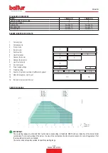
BURNER IDENTIFICATION PLATE

Company logo

Company name

Product code

Burner model

Serial number

Liquid fuel power

Gaseous fuel power

Gaseous fuel pressure

Liquid fuel viscosity

10 

Fan motor power

11 

Power supply voltage

12 

Protection rating

13 

Country of origin and numbers of certificate of approval

14 

Manufacturing date - month / year

15 

-

16 

Bar code serial number of burner

1

2

3

4

5

6

7

11

14

12

Targa_descr_bru

8

9

10

13

16

15

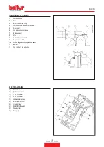
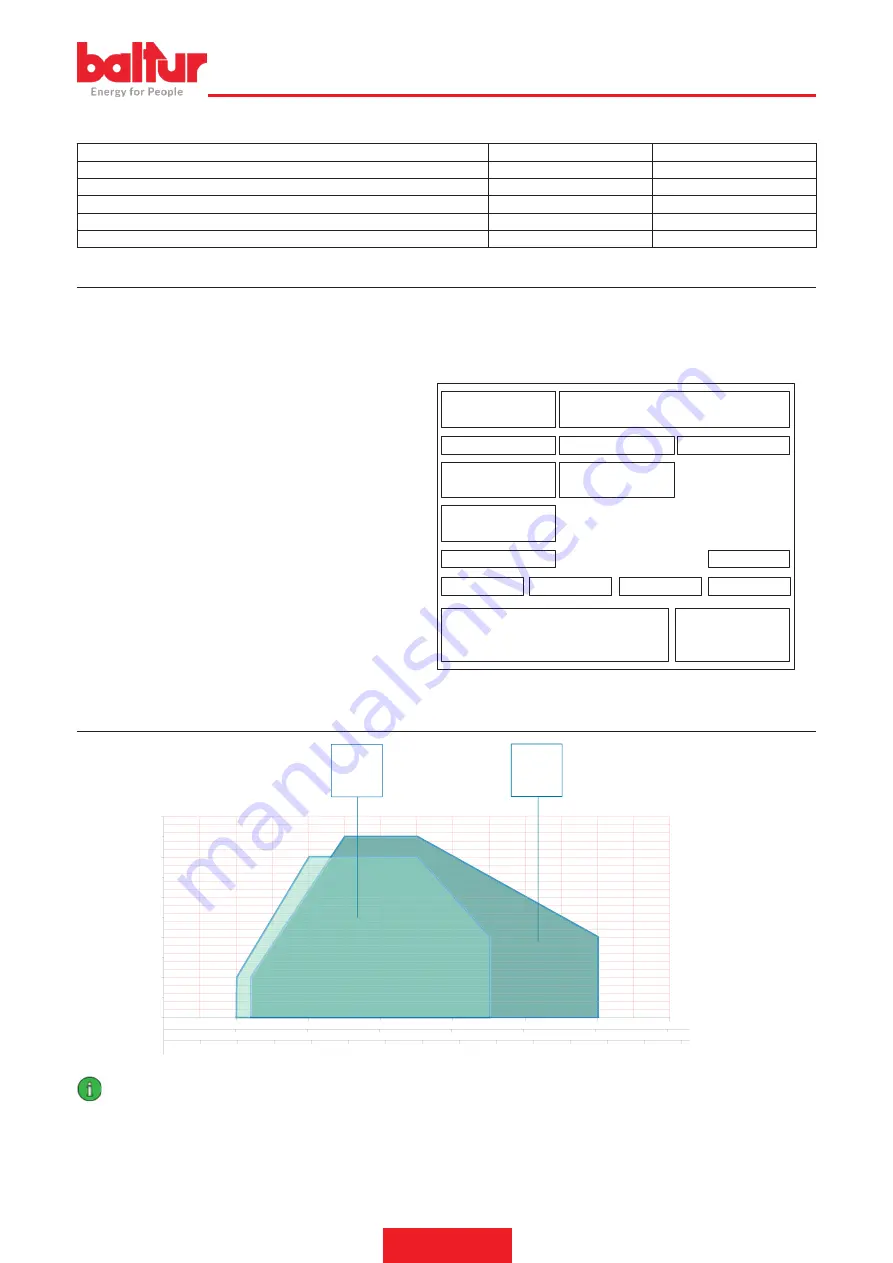
OPERATING RANGE

2

0

mbar

0002922650

100

kW

TBG 45P

10

200

300

400

500

600

700

4

6

8

10

3

3

m /h(Metano)
m /h(G.P.L.)

n
n

20

30

40

50

60

70

2

4

6

8

10

12

14

16

18

20

22

24

26

28

TBG 45ME

TBG 60P

TBG 60PN

TBG 45PN

TBG 60ME

TBG 45P-V

TBG 60P-V

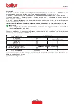
IMPORTANT

The operating ranges are obtained from test boilers corresponding to Standard EN676 and are indicative of the burner-boiler 

combination. For correct working of the burner, the size of the combustion chamber must correspond to current regulations; if not 

the manufacturers must be consulted.

The burner shall not operate outside its specific operating range.

Summary of Contents for TBG 45 PV

Page 1: ...GAS BURNER WITH INVERTER ITALIANO Manuale istruzioni per l installazione l uso e la manutenzione IT Instruction manual for installation use and maintenance EN TBG 45 P V TBG 60 P V ISTRUZIONI ORIGINA...

Page 2: ......

Page 3: ...i elettrici 13 Descrizione del funzionamento 15 Accensione e regolazione 16 Pressostato aria in secondo stadio 17 REGOLAZIONE POSIZIONE TIRANTE DI AZIONAMENTO FARFALLA GAS 19 Corrente ionizzazione 20...

Page 4: ...NOx V per inverter FGR per ricircolazione esterna fumi rispettano i requisiti minimi imposti dalle Direttive e Regolamenti europei UE 2016 426 R A G 2014 30 UE C E M 2014 35 UE D B T 2006 42 CE D M e...

Page 5: ...occaggio di 3 anni AVVERTENZE GENERALI La data di produzione dell apparecchio mese anno sono indicati sulla targa identificazione bruciatore presente sull apparecchio L apparecchio non adatto a essere...

Page 6: ...o dalla loro sede Rendere innocue quelle parti che potrebbero essere potenziali fonti di pericolo AVVERTENZE PER L AVVIAMENTO IL COLLAUDO L USO E LA MANUTENZIONE L avviamento il collaudo e la manutenz...

Page 7: ...rga Prevedere un interruttore onnipolare con distanza d apertura dei contatti uguale o superiore a 3 mm per l allacciamento alla rete elettrica come previsto dalle normative di sicurezza vigenti condi...

Page 8: ...I ALIMENTAZIONE 60 Hz 1N 230V 10 1N 400V 10 GRADO DI PROTEZIONE IP 44 IP 44 RILEVAZIONE FIAMMA SONDA IONIZZAZIONE SONDA IONIZZAZIONE REGOLAZIONE PORTATAARIA SERVOMOTORE ELETTRICO CAMMA ELETTRONICA PRE...

Page 9: ...i certificato di omologazione 14 Data di produzione mese anno 15 16 Codice a barre matricola bruciatore 1 2 3 4 5 6 7 11 14 12 Targa_descr_bru 8 9 10 13 16 15 CAMPO DI LAVORO 2 0 mbar 0002922650 100 k...

Page 10: ...GOMBRO Modello A A1 A2 B B1 B2 B6 C TBG 45 P V 550 270 280 435 325 108 160 920 TBG 60 P V 550 270 280 455 325 130 160 920 Modello D E F I I1 L M N TBG 45 P V 140 300 137 133 215 215 200 245 M12 145 TB...

Page 11: ...otore 9 Servomotore regolazione aria 10 Pressostato aria 10a Pressostato di controllo pressione aria in secondo stadio 11 Inverter 12 Tirante di azionamento farfalla gas QUADRO ELETTRICO 13 Apparecchi...

Page 12: ...alvole Corredato di connettori a 4 e a 7 poli 1 flangia e 1 guarnizione isolante per il fissaggio alla caldaia Uscita rampa gas dal basso CARATTERISTICHE COSTRUTTIVE Il bruciatore risulta composto da...

Page 13: ...sia applicato su tubazione orizzontale dopo il filtro Il regolatore di pressione del gas deve essere regolato mentre lavora alla massima portata effettivamente utilizzata dal bruciatore La pressione...

Page 14: ...consigliata dal costruttore del generatore Fissare il bruciatore alla caldaia 1 tramite i prigionieri le rondelle e i relativi dadi in dotazione 7 CAUTELA AVVERTENZE Sigillare completamente con materi...

Page 15: ...re un interruttore onnipolare con distanza d apertura dei contatti uguale o superiore a 3 mm per l allacciamento alla rete elettrica come previsto dalle normative di sicurezza vigenti Per i collegamen...

Page 16: ...lsiasi intervento sull apparecchiatura attendere sempre cinque minuti dopo averla disattivata CAUTELA AVVERTENZE L apertura del quadro elettrico del bruciatore consentita esclusivamente a personale pr...

Page 17: ...ntemporaneamente la rotazione del servomotore 1 porta la serranda dell aria nella posizione di apertura corrispondente alla seconda fiamma pertanto la fase di preventilazione avviene con serranda aria...

Page 18: ...fiamma stabile Il blocco con presenza di fiamma pu essere causato da instabilit della stessa nella zona di ionizzazione per un rapporto aria gas non corretto Si rimedia variando la quantit di aria e...

Page 19: ...golate per il primo stadio di funzionamento Una volta effettuata la regolazione del primo stadio occorre spegnere il bruciatore e verificare che l accensione non sia rumorosa In caso di pulsazioni all...

Page 20: ...di circuito di qualsiasi pressostato quando il bruciatore in funzione fiamma accesa determina immediatamente l arresto del bruciatore Alla prima accensione del bruciatore indispensabile verificare il...

Page 21: ...le dei bruciatori nella maggioranza delle applicazioni tuttavia in alcuni casi conviene modificare la posizione di fissaggio degli snodi su una o entrambe le leve vedi tabella Per modificare la posizi...

Page 22: ...urare il valore della corrente di ionizzazione il cui valore minimo per assicurare il funzionamento dell apparecchiatura riportato nello schema elettrico specifico Terminata la misurazione ripristinar...

Page 23: ...della serranda aria che regola il flusso all aspirazione del ventilatore bruciatore ovviamente questa condizione si deve verificare quando il bruciatore lavora alla massima erogazione desiderata Si de...

Page 24: ...agnosi premere per almeno 3 secondi il pulsante di sblocco un lampeggio veloce di colore rosso indicher che la funzione attiva analogamente per disattivare la funzione baster premere per almeno 3 seco...

Page 25: ...icurezza TSA Malfunzionamento valvole combustibile Malfunzionamento rilevatore fiamma Difettosit nella taratura del bruciatore assenza di combustibile Mancata accensione difettosit trasformatore di ac...

Page 26: ...ressostato gas H Interruttore principale HS Contatto ausiliario rel ION Sonda di Ionizzazione K1 4 Rel Interni KL Fiamma bassa LK Serranda dell Aria LKP Posizione della serranda dell aria LP Pressosta...

Page 27: ...z sulla frequenza del segnale in uscita dall inverter Per variare in modo rapido la frequenza basta tenere premuto per un tempo prolungato massimo 16 secondi uno dei due tasti Il motore segue la regol...

Page 28: ...Durante la scarica dei condensatori si possono osservare i led lampeggiare rapidamente Una volta che i led smettono di lampeggiare in modo rapido significa che la scarica dei condensatori avvenuta a...

Page 29: ...polvere o sporcizia N 4 led verdi accesi led rosso N 3 acceso La tensione elettrica di alimentazione del bruciatore ha raggiunto valori non accettabili Sbalzi di tensione sulla linea elettrica di alim...

Page 30: ...inverter 2 fiamma 40 V Camma inserzione pressostato aria 2 fiamma 80 1 Perno inserzione ed esclusione accoppiamento motore albero camme 2 Camme regolabili 3 Scala di riferimento 4 Indicatore di posiz...

Page 31: ...el seguente modo Svitare le viti di fissaggio 6 e rimuovere il coperchio 11 Assicurarsi che la piastrina mobile 23 sia tenuta bloccata dalla vite 8 Questo consentir una volta terminate le operazioni d...

Page 32: ...NETTI ANNO CAMMA MECCANICA VERIFICA USURA E FUNZIONALIT INGRASSAGGIO PATTINO E VITI ANNO LEVE TIRANTI SNODI SFERICI CONTROLLO EVENTUALI USURE LUBRIFICAZIONE COMPONENTI ANNO IMPIANTO ELETTRICO VERIFICA...

Page 33: ...in contratti e o note di consegna o di pagamento sono indipendenti e non fanno riferimento alla vita attesa di seguito indicata Per condizioni operative normali si intendono applicazioni su caldaie a...

Page 34: ...3 Posizionare le feritoie C a filo disco fiamma D come rappresentato in figura bloccare in modo adeguato le nuove riduzioni agendo sulle rispettive viti CAUTELA AVVERTENZE In alcune particolari appli...

Page 35: ...gas non stata adeguatamente sfogata dall aria caso di prima accensione 3 La pressione del gas insufficiente o eccessiva 4 Passaggio aria tra disco e testa troppo chiuso RIMEDIO 1 Invertire l alimentaz...

Page 36: ...ITALIANO 34 35 0006081444_201610 SCHEMI ELETTRICI...

Page 37: ...NIMA Pm PRESSOSTATO DI MINIMA S1 INTERRUTTORE MARCIAARRESTO S2 PULSANTE SBLOCCO SG INTERRUTTORE GENERALE T2 TERMOSTATO 2 STADIO TA TRASFORMATORE D ACCENSIONE TC TERMOSTATO CALDAIA TS TERMOSTATO DI SIC...

Page 38: ...13 Operating description 15 Starting up and regulation 16 Second stage air pressure switch 17 TIE ROD POSITION ADJUSTMENT FOR GAS THROTTLE ACTIVATION 19 Ionisation current 20 Diagram for regulating th...

Page 39: ...verter FGR for fume external recirculation respect the minimal regulations of the European Directives and Regulations UE 2016 426 R A G 2014 30 UE C E M 2014 35 UE D B T 2006 42 CE D M and have been d...

Page 40: ...d conditions with temperature between 25 C and 55 C The storage time is 3 years GENERAL WARNINGS The equipment production date month year is written on the burner identification plate located on the e...

Page 41: ...ecting the power cable from the main switch Cut off the fuel supply using the shut off valve and remove the control wheels from their position Render harmless any potentially dangerous parts WARNINGS...

Page 42: ...supply connection is required an omnipolar switch with a contact opening gap equal or above 3 mm in accordance with current safety regulations condition of overvoltage category III Removetheexternalin...

Page 43: ...0V 10 60 Hz POWER SUPPLY VOLTAGE 1N 230V 10 1N 400V 10 PROTECTION RATING IP 44 IP 44 FLAME DETECTION IONISATION PROBE IONISATION PROBE AIR FLOW RATE REGULATION ELECTRIC SERVOMOTOR ELECTRONIC CAM SOUND...

Page 44: ...pproval 14 Manufacturing date month year 15 16 Bar code serial number of burner 1 2 3 4 5 6 7 11 14 12 Targa_descr_bru 8 9 10 13 16 15 OPERATING RANGE 2 0 mbar 0002922650 100 kW TBG 45P 10 200 300 400...

Page 45: ...SIONS Model A A1 A2 B B1 B2 B6 C TBG 45 P V 550 270 280 435 325 108 160 920 TBG 60 P V 550 270 280 455 325 130 160 920 Model D E F I I1 L M N TBG 45 P V 140 300 137 133 215 215 200 245 M12 145 TBG 60...

Page 46: ...e 7 Electrical panel 8 Motor 9 Air regulation servomotor 10 Air pressure switch 10a Second stage air control pressure switch 11 Inverter 12 Gas throttle tie rod activation ELECTRICAL PANEL 13 Control...

Page 47: ...a kit for valve seal control Equipped with 4 and 7 pole connectors 1 flange and 1 insulating seal for fixing to the boiler Gas train exit from below DESIGN CHARACTERISTICS The burner consists of Comb...

Page 48: ...lter The gas pressure regulator must be adjusted when it is working at the maximum output actually used by the burner The outgoing pressure must be adjusted to a value slightly below the maximum possi...

Page 49: ...recommended by the generator manufacturer Fasten the burner to the boiler 1 by means of the stud bolts washers and the nuts provided 7 CAUTION WARNINGS Completely seal the space between the burner sl...

Page 50: ...e burner For the mains supply connection is required an omnipolar switch with a contact opening gap equal or above 3 mm in accordance with current safety regulations Refer to the wiring diagram for el...

Page 51: ...l Before performing any operation on the equipment wait five minutes after deactivating it CAUTION WARNINGS Only professionally qualified personnel may open the burner electrical switchboard CAUTION W...

Page 52: ...omotor 1 puts the air damper into the open position corresponding to the second flame as a result the pre ventilation phase comes only with the air damper in the second flame position At the end of th...

Page 53: ...t enough gas to provide a stable flame The lock out with flame present may be caused by instability in the ionisation area due to an incorrect air gas ratio This can be solved by changing the amount o...

Page 54: ...tage operation Once adjustment of the first stage has been carried out the burner needs to be switched off with verification that the ignition is not noisy In the event of pulsations during ignition i...

Page 55: ...s the burner to stop immediately When first switching on the burner it is essential to check that they work properly Check the triggering of the flame detector ionisation electrode Disconnect the jump...

Page 56: ...burner operation in the majority of applications although in some cases it is better to modify the position of the joints on one or both of the levers see table The modify the position of the tie rod...

Page 57: ...ll be possible to measure the ionisation current the minimum value of which to ensure the working of the equipment is shown in the specific wiring diagram At the end of the measurement connect the jum...

Page 58: ...ening of the air lock that regulates the burner fan intake flow Obviously this condition must occur when the burner operates at the maximum required output Start by adjusting the device that closes th...

Page 59: ...on hold the reset button down for at least 3 seconds A quick red flashing indicates that the function is active Likewise hold the reset button down for at least 3 seconds to deactivate the function th...

Page 60: ...al 10 Possible causes 2 blinks On No flame at the end of the safe ignition time TSA Fuel valves malfunctioning Flame detector malfunctioning Incorrect burner calibration no fuel No ignition faulty ign...

Page 61: ...ressure switch H Main switch HS Auxiliary contactor relay ION__tab_Ionisation probe K1 4 Internal Relays KL Low flame LK Air damper LKP Air damper position LP Air pressure switch LR Modulation M Fan m...

Page 62: ...2 Hz to the inverter output signal To quickly change the frequency hold one of the two the buttons down for a prolonged period maximum 16 seconds The motor follows the adjustment by increasing or decr...

Page 63: ...arge of the condensers the LEDs will flash rapidly Once the LEDs have stopped flashing rapidly this means that the discharge of the condensers has finished at this point restore power to the burner an...

Page 64: ...is not clogged by dust or dirt No 4 green LEDs on red LED No 3 on The burner power supply voltage has reached unacceptable values Power surges in the electrical supply line Check that the line is with...

Page 65: ...am 30 IV 2nd flame inverter actuating cam 40 IV 2nd flame air pressure switch actuating cam 80 1 Motor camshaft coupling On Off pin 2 Adjustable camshafts 3 Reference scale 4 Position indicator TO MOD...

Page 66: ...s 6 and remove the lid 11 Make sure that the mobile plate 23 is fastened by the screw 8 Once the maintenance operations have been completed this will make it possible to return the mixer assembly to t...

Page 67: ...ING FAN CLEANING BEARING NOISE CHECK YEAR MECHANICAL CAM CHECK OF WEAR AND OPERATION GREASING OF SLIDING BLOCK AND SCREWS YEAR LEVERS TIE RODS BALL JOINTS CHECK OF ANY WEAR COMPONENT LUBRICATION YEAR...

Page 68: ...rranty conditions laid down in contracts and or delivery or payment notes if necessary are independent and do not refer to the expected lifespan stated below Normal operating conditions means applicat...

Page 69: ...rt of the mixer 0002935830c 3 Position the slits C flush with the flame disc D as shown in the figure suitably secure the new reducers using the corresponding screws CAUTION WARNINGS In some particula...

Page 70: ...properly bled of air in the case of first ignition 3 The gas pressure is insufficient or excessive 4 Air flow between disk and head too narrow REMEDY 1 Invert the ignition transformer power supply 23...

Page 71: ...ENGLISH 34 35 0006081444_201610 WIRING DIAGRAMS...

Page 72: ...PRESSURE SWITCH Pm MINIMUM PRESSURE SWITCH S1 START STOP SWITCH S2 RELEASE BUTTON SG MAIN SWITCH T2 2ND STAGE THERMOSTAT TA IGNITION TRANSFORMER TC BOILER THERMOSTAT TS SAFETY THERMOSTAT X1 BURNER TE...

Page 73: ......
Page 74: ...Il presente catalogo riveste carattere puramente indicativo La casa pertanto si riserva ogni possibilit di modifica dei dati tecnici e di quant altro in esso riportato Information contained in this c...

Reviews: