19 / 26
0006081362_20
1403
0002934700
ENGLISH
•
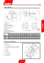
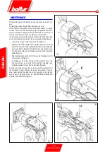
To complete the operation fix the flame pipe to the scroll burner
and finally reposition the mixing unit in the relative housing.
At this point it is possible to install the burner in the boiler with the
valve train as shown in configuration 9 illustrated in paragraph
"Gas train assembly".
TWO STAGE GAS-FIRED BURNER
It is normally not advisable to connect a burner working on a boiler
for heating water for two-flame working. The burner can also work
for long periods of time with one flame alone. The boiler is insuffi-
ciently loaded and so come out at too low a temperature (less than
dew point) giving rise to the presence of condensation water in
the flue. When the two-flame burner is installed on a boiler for the
production of hot water for heating, it must be connected in such
a way as to work normally with both flames completely stopping,
without changing to the first flame, when the preset temperature
has been reached. For this type of working the thermostat for the
second flame is not installed and a direct connection is made (jum-
per) between the equipment’s terminals.
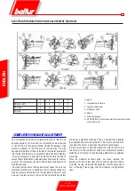
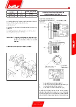
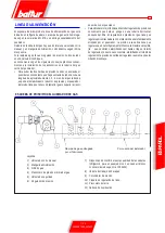
SINGLE STAGE AIR BURNER TBG
45 - 60 ADJUSTMENT SCHEME
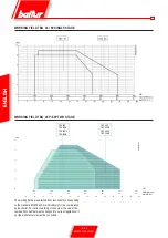
To adjust the angle of opening of the air damper, slacken the screw
(1) and turn the hand wheel (2) to bring the index to the desired
position. Subsequently tighten the screw to lock the damper.
Position 0: air damper fully closed.
Position 6: air damper fully open.
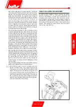
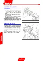
PREPARATION FOR CONNECTION
WITH TRAIN TURNED UPWARDS
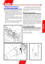
If you wish to turn the train entrance upwards, before applying the
burner to the boiler, follow the subsequent procedure.
•
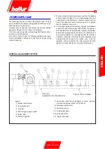
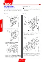
Following the instructions detailed in the "Maintenance"
paragraph, extract the mixer assembly and remove the screw
(1) which connect the unit’s forward movement rod (2) to the
gas delivery pipe (3). Remove the screw (5) which connects the
gas mixer (6) to the pipe (figure 1).
•
Turn the bend coupling through 180° (4) and the mixer (6), in
such a way that the inlet gas is turned upwards (figure 1). Again
fix the mixer and the unit’s forward movement rod to the gas
delivery pipe.
•
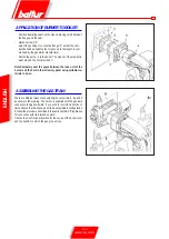
Now remove the 4 nuts (7) in figure 2, disassemble the flame
pipe (8) from the relative stud bolts, reposition them with the
threaded connection for fixing the gas train upwards.
fig. 1
fig-2
Summary of Contents for TBG 45
Page 2: ......
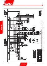
Page 24: ...22 26 0006081362_201403 ENGLISH ...
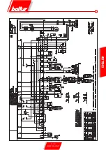
Page 25: ...23 26 0006081362_201403 ENGLISH ...
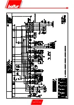
Page 26: ...24 26 0006081362_201403 ...
Page 27: ...25 26 0006081362_201403 ...
Page 50: ...22 26 0006081362_201403 ESPAÑOL ESQUEMA ELECTRICO ...
Page 51: ...23 26 0006081362_201403 ESPAÑOL ...
Page 52: ...24 26 0006081362_201403 ...
Page 53: ...25 26 0006081362_201403 ...
Page 76: ...22 26 0006081362_201403 FRANÇAIS SCHEMA ELECTRIQUE ...
Page 77: ...23 26 0006081362_201403 FRANÇAIS ...
Page 78: ...24 26 0006081362_201403 ...
Page 79: ...25 26 0006081362_201403 ...
Page 102: ...22 26 0006081362_201403 TÜRKÇE ELEKTRİK ŞEMASI ...
Page 103: ...23 26 0006081362_201403 TÜRKÇE ...
Page 104: ...24 26 0006081362_201403 ...
Page 105: ...25 26 0006081362_201403 ...
Page 130: ...24 26 0006081362_201403 ...
Page 131: ...25 26 0006081362_201403 ...
Page 154: ...22 26 0006081362_201403 中 文 电气图 ...
Page 155: ...23 26 0006081362_201403 中 文 ...
Page 156: ...24 26 0006081362_201403 ...
Page 157: ...25 26 0006081362_201403 ...
Page 159: ......

