9 / 15
0006081370_200807
E
N
G
L
I
S
H
DESCRIPTION OF OPERATIONS AT TWO STAGE
PROGRESSIVE
These burners are of the blown air type which have a mixture of
gas/air at the combustion head. They are suitable for use with
combustion chambers which are either raising high pressure or
reducing pressure, according to the relative work curves. Together
with excellent flame stability, these burners are safe and highly
efficient. It is equipped with a steel flange which slips on the bur
-
ner head. When fastening the burner to the boiler it is necessary
to correctly position the flange so that the burner head enters the
combustion chamber to the extent specified by the boiler ma
-
nufacturer.The burner has an electronic cam mod. MPA22. The
microprocessor-controlled MPA22 provides intermittent operation,
controls and monitors the electronically-modulated fan-equipped
gas burners and features two (air/gas) adjuster motors. When wor
-
king as an automatic burner valve seal control is activated; (for a
better understanding of the MPA 22 read the instructions in the
attached manual, code 0006080905).
Operation of is of the progressive two-stage type, so called becau
-
se the switch from primary flame to secondary flame (from mini
-
mum to the set maximum) occurs gradually as regards the delivery
of both combustion air and fuel; this gives considerable advanta
-
ges in terms of the pressure stability in the gas feed line. Delivery
rate ranges, approximately, from 1 to 1/3. Ignition is preceded by
pre-ventilation of the combustion chamber as per standards, with
the air open: this lasts about 36 seconds. If, at the end of the ven
-
tilation stage, the air pressure switch detects that pressure is suffi
-
cient, the ignition transformer comes on and, after 3 seconds, the
safety and main valves open in sequence. The gas reaches the
combustion head, is mixed with the air being delivered by the fan,
and is ignited. Delivery is regulated by the gas throttle valve. Three
seconds after the (main and safety) valves are opened the ignition
transformer is switched off. The burner is now on at the ignition
point (P0). The flame is detected by the relative control device (an
ionisation sensor positioned inside the flame).The programming
relay goes beyond the shutdown position and powers the air/gas
delivery regulation servomotors, which go to minimum (P1). If the
2nd stage boiler thermostat (or pressure switch) – adjusted by a
temperature or
pressure greater than that in the boiler) allow, the air/gas delivery
servomotors start running and cause a gradual increase is the de
-
livery of gas and combustion air until the maximum flow rates to
which the burner has been set have been reached (point P9).
N.B. Electronic cam MPA22 controls the burner by adjusting
the combustion air and gas servomotors according to a pre-
set curve.
The burner remains in the maximum delivery position until the tem
-
perature or pressure reaches the limit set for the intervention of the
boiler thermostat (or pressure switch) of the 2nd stage and makes
the servomotors regulating gas/air delivery rotate in the opposite
sense of direction. Thus gas delivery and the relative combustion
air are gradually reduced until they reach minimum value.
Even with delivery at a minimum, if the limit (temperature or pres
-
sure at the shut down device (thermostat or pressure switch) has
been regulated is reached, the burner will be brought to a stan
-
dstill. When the temperature or pressure drops below the inter
-
vention limit set on the shut down device, the burner will star up
again, according to the programme previously described. During
normal operations, the boiler thermostat (or pressure switch) of
the 2nd stage fitted to the boiler detects the variations requested
and automatically proceeds with adapting the fuel and combustion
air delivery by inserting the servomotors which regulates delivery
(gas/air). This will rotate in such a way as to obtain an increase or
a decrease. With this manoeuvre, the gas/air delivery regulating
system try’s to equilibrate the quantity of heat supplied to the boiler
with that which the boiler gives to be utilised.
If the flame does not appear within THREE seconds of the opening
of the gas valve, the control box goes to “shut down” (the burner
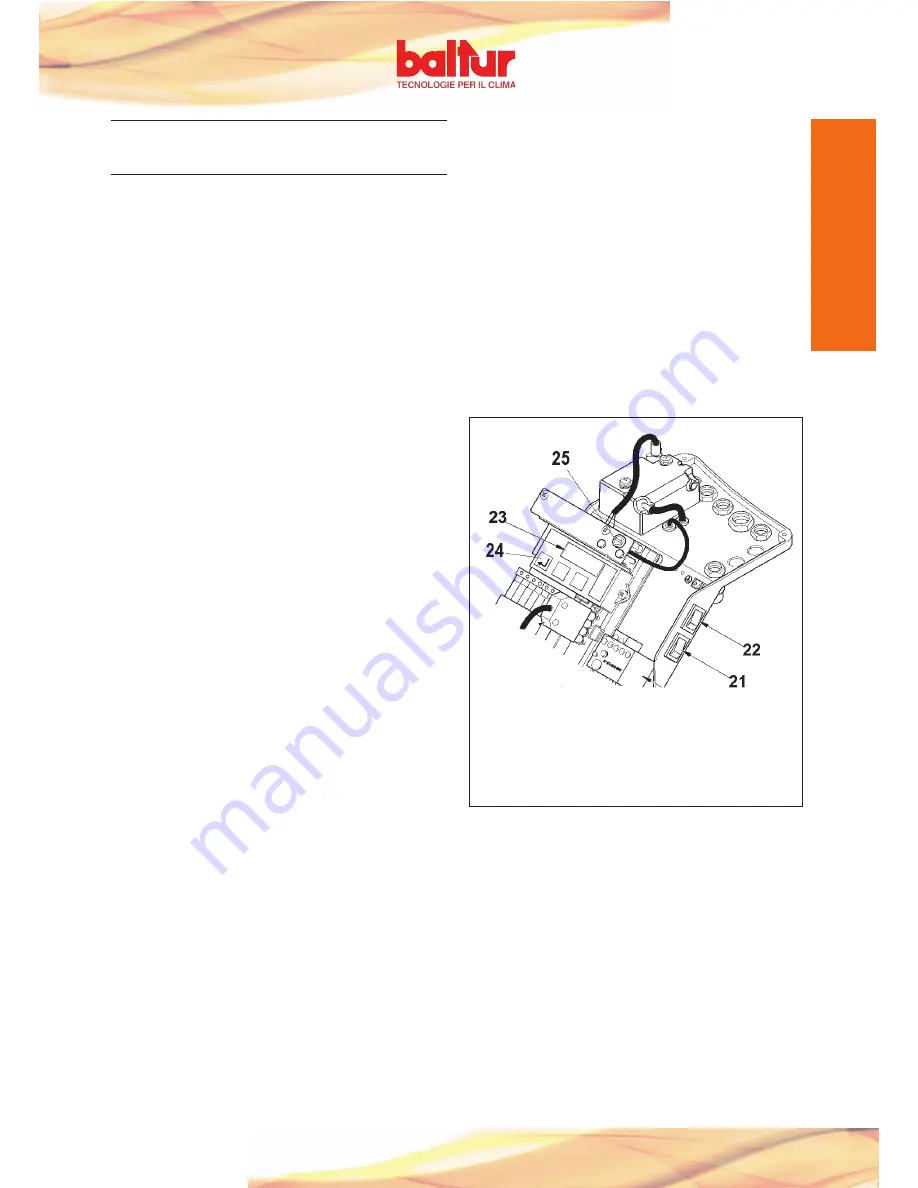
stops completely and error message 25H) on display. (23)
To “unblock” the equipment press the interference elimination but
-
ton for about half a second (24).
0002935870n1
21) Thermostatic line switch
22) START/STOP switch
23) Display MPA22
24) Confirm or interference recovery key
25) Fuse
Summary of Contents for TBG 45ME
Page 2: ......
Page 4: ......
Page 6: ......
Page 22: ......
Page 38: ......
Page 54: ......
Page 70: ......
Page 86: ......
Page 102: ......
Page 103: ...97 101 0006081368_200807 ...
Page 104: ...98 101 0006081368_200807 ...
Page 105: ...99 101 0006081368_200807 ...


