background image

35 / 75

0006081327_200807

E

N
G

L

I

S

H

TWO-STAGE GAS BURNERS: TROUBLE-SHOOTING GUIDE

POSSIBLE CAUSE

1)  Disturbance to ionization current from 

ignition transformer.

2)   Flame sensor (ionization probe) ineffi

-

cient.

3)  Flame sensor (ionization probe) position 

incorrect.

4)  Ionization  probe  or  relative  earth  ca-

ble.

5)  Electrical  connection  cut-off  by  flame 

sensor.

6)  Inefficient  draught  or  fumes  passage 

blocked.

7)  Flame disk or combustion heads dirty 

or worn.

8)  Equipment fault.
9)   No ionization. 

1)  Fault in ignition circuit.

2)  Ignition transformer cable discharges to 

earth.

3)  Ignition  transformer  cable  discon-

nected.

4)  Ignition transformer faulty.
5)  The  distance  between  electrode  and 

earth is incorrect.

6)  Isolator  dirty,  so  electrode  discharges 

to earth. 

1)  air/gas ratio incorrect.

2)  Gas pipe has not been properly bled of 

air (in the case of first ignition).

3)  The  gas  pressure  is  insufficient  or 

excessive.

4)  Air  flow  between  disk  and  head  too 

narrow. 

SOLUTION

1)  Invert the ignition transformer power 

supply (230V side) and check using 

an analog micro-ammeter.

2)  Replace flame sensor.

3)  Correct the position of the flame sen

-

sor, and then check its efficiency by 

inserting the analog micro-ammeter.

4)  Check visually and using the instru

-

ment.

5)  Restore the connection.

6)  Ensure that the boiler fumes passage 

and chimney connection are free.

7)  Visually check and replace, if neces

-

sary.

8)  Replace.
9)  If the “earth” of the apparatus is not 

efficient, do not check the ionization 
current.  Check  the  efficiency  of  the 

“earth”  at  the  terminal  concerned 
of  the  apparatus  and  at  the  “earth” 

connection of the electric system.

1)  Check the ignition transformer power 

supply (230V) and high voltage circuit 
(electrode to earth or isolator broken 
under locking terminal).

2)  Replace.

3)  Connect.

4)  Replace.
5)  Position at the correct distance.

6)  Clean or replace isolator and electro-

de.


1)  Correct the air/gas ratio (there is pro-

bably too much air or very little gas).

2)  Bleed the gas pipe again, taking great 

care.

3)  Check  the  maximum  gas  pressure 

value 

at the time of ignition

 (use a 

water pressure gauge, if possible).

4)  Adjust the disk/head opening. 

DETAILS OF PROBLEM

The apparatus goes into “lock-out” with 

the flame (red light on).
Fault  restricted  to  flame  control  devi

-

ce.


The apparatus goes into “lock-out”, gas 
flows out, but there is no flame (red light 
on).Fault restricted to ignition circuit.


The  apparatus  goes  into  “lock-out”, 
gas  flows  out,  but  there  is  no  flame 
(red light on).

Summary of Contents for TBG 50LX PN

Page 1: ...Instruction for burners model Instrucci nes para quemadores modelos Mode d emploi brule r TBG50LXPN TBG80LXPN TBG110LXPN TBG140LXPN TBG200LXPN 0006081327_200807 IT GB SP FR TBG50LXPN V TBG80LXPN V TBG...

Page 2: ......

Page 3: ...rialirispet tano i requisiti minimi imposti dalle Direttive Europee 90 396 CEE Direttiva Gas 92 42 CEE Direttiva Rendimenti 89 336 CEE Direttiva Compatibilit e m 73 23 CEE Direttiva Bassa Tensione 98...

Page 4: ...ario o se si dovesse traslocare e lasciare l apparecchio assicurarsi sempre che il libretto accompagni l apparecchio in modo che possa essere consultato dal nuovo proprietario e o dall installatore Pe...

Page 5: ...trebbero compromettere il buon funzionamento del bruciatore Per la prima messa in funzione dell apparecchio far effettuare da personale professionalmente qualificato le seguenti verifiche a il control...

Page 6: ...ce accordingly Gas Appliances Directive 0 396 EEC made by CE0085 DVGW The Vice President and Managing Director Dr Riccardo Fava GB Before using the burner for the first time please carefully read the...

Page 7: ...If the equipment is sold or transferred to another owner or if the owner moves and leaves the equipment make sure that the booklet always goes with the equipment so it can be consulted by the new owne...

Page 8: ...d out by qualified technicians and in compliance with current law and regulations since incorrect installation may cause damage to person animals or things for which damage the manufacturer shall not...

Page 9: ...IP 44 FLAME DETECTOR SONDA DI IONIZZAZIONE NOISE dBA 72 73 75 5 79 85 WEIGHT kg 76 78 87 91 94 Natural Gas G 20 FLOW RATE MAX m n h 55 3 80 5 120 7 145 8 191 1 MIN m n h 11 13 1 18 1 20 1 47 8 PRESSU...

Page 10: ...0 540 380 160 1280 200 450 240 219 320 280 370 M12 250 260 12 112 5 54 TBG 200LX PN 645 275 370 540 380 160 1280 200 450 250 219 320 280 370 M12 255 260 12 112 5 54 1 Combustion head 2 Gasket 3 Burner...

Page 11: ...h 5 Safety valve 6 Pressure regulator 7 Valves seal control device obligatory for burner with maximum nominal thermal output Gas train supplied by the manufacturer The job of the installer The gas sup...

Page 12: ...boiler s shutter Tube fixing screw Combustion chamber pressure detection stiff tube Combustion chamber pressure detection point Cut in line with diffuser Combustion chamber pressure transmission tube...

Page 13: ...rn the cam 6 so that the float exerts sufficient pressure on the two cables then tighten the screws that fasten the cable float Finally connect the two 7 and 4 pole plugs IMPORTANT the housings for th...

Page 14: ...set maximum If there is no flame the control box stops in its safety lock out LED 7 within 3 seconds from the opening of the main valve In the case of safety lock out the valves immediately close agai...

Page 15: ...xtraneous light when burner startup 5 blinks l l l l l On Time out LP LP is welded in working position 6 blinks l l l l l l On Free 7 blinks l l l l l l l On Too many losses of flame during operation...

Page 16: ...for ignition Check during preventilation that the pressure switch that controls air pressure in fact exchanges from the closed position where no pressure is detected it must pass to the closed positi...

Page 17: ...heck the triggering that leads to immediate lock out of the burner To release the locked burner press the release button and reset the pressure switch to a value sufficient to detect the existing air...

Page 18: ...NISATION PROBE ADJUSTMENT DIAGRAM Legend 1 Ionisation electrode 2 Ignition electrode 3 Deflector disk 4 Mixer 5 Gas outlet pipe Mod A B C TBG 50LX PN 5 3 3 TBG 80LX PN 5 8 TBG 110LX PN 5 5 TBG 140LX P...

Page 19: ...ulates the aspiration flow from the burner fan This must of course be the case when the burner is working at maximum desired supply In practice you have to start the adjustment with the device that cl...

Page 20: ...sure successful disassembly of the mixing unit With the same wrench turn the ball joint 6 in the direction indica ted with the arrow unhooking the lever that moves the combustion head forward figure 2...

Page 21: ...34 75 0006081327_200807 E N G L I S H CAMS REGULATION SERVOMOTOR SQN 72 6A4A20 N 0002933651 rev 14 02 2007...

Page 22: ...or and then check its efficiency by inserting the analog micro ammeter 4 Check visually and using the instru ment 5 Restore the connection 6 Ensure that the boiler fumes passage and chimney connection...

Page 23: ...72 75 0006081327_200807...

Page 24: ...73 75 0006081327_200807...

Page 25: ...74 75 0006081327_200807...

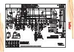
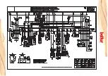
Page 26: ...AX P1 CONTAORE HOUR METER COMPTEUR HORAIRE CONTADOR DE HORAS PA PRESSOSTATO ARIA AIR PRESSURE SWITCH PRESSOSTAT AIR PRESOSTATO AIRE Pm PRESSOSTATO DI MINIMA GAS MIN PRESSURE SWITCH PRESSOSTAT MIN PRES...

Page 27: ...La Casa por lo tanto se reserva cualquier posibilitad de modificati n de datos t cnicos y otras anotaciones Ce manuel rev t caract re purement indicatif La maison se reserve la possibilit de modifier...

Reviews: