7 / 15
0006081083_200705
E
N
G
L
I
S
H
APPLICATION OF BURNER TO BOILER
HEAD UNIT ASSEMNLY
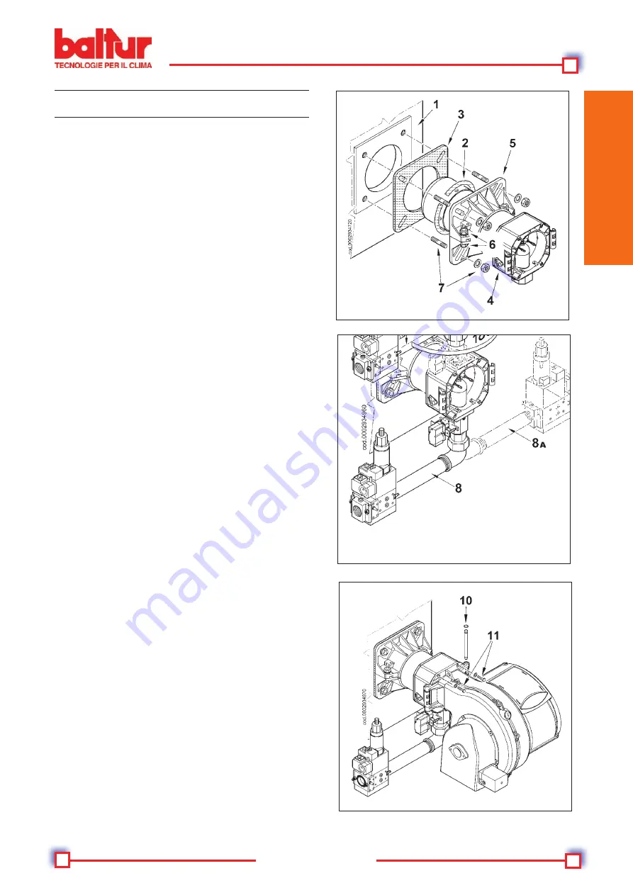
A) Adjust the position of connector flange 5 by loosening the
screws 6 so that the combustion head penetrates the advised
amount into the combustion chamber as recommended by the
generator’s manufacturer.
B) Position the seal insulation 3 on the tube unit inserting cord 2
between flange and seal.
C) Fasten the Combustion Head unit 4 to the boiler 1 by means
of the stud bolts, washers and
the nuts provided 7.
Note:Competely seal the space between the tube unit of the bur
-
ner and the hole in the refractory panel using suitable materials to
do so.
GAS TRAIN ASSEMBLY
There are different assembly possibilities 8, 8a, 9 of the valves
train as shown in the diagram alongside.
Select the best position according to the particular arrangement of
the boiler room and the gas piping’s entry position.
N.B. In the case of very large vales e.g. DN65 or DN80, make
sure there is sufficient support to prevent excessive stresses on
the gas train connector.
ASSEMBLYOFVENTILATION SYSTEM
A) Position the half-hinge on the burner scroll in line with those
on the combustion head assembly.
B) Put the hinge pin 10 in the position considered most suitable.
C) Connect the cables (switch on
and ionisation) to the
corresponding electrodes, close the hinge, locking the burner
by means of screws 11.
Summary of Contents for TBG 55ME
Page 2: ......
Page 4: ......
Page 6: ......
Page 22: ......
Page 38: ......
Page 54: ......
Page 70: ......
Page 86: ......
Page 102: ...99 102 0006081083 _200705 ...
Page 103: ...100 102 0006081083 _200705 ...


