Page 1: ...Istruzioni per bruciatori modello Instruction for burners model Instrucci nes para quemadores modelos Mode d emploi brule r TBG55PN TBG85PN 0006081042_200705 IT GB SP FR TBG120PN TBG150PN TBG210PN...
Page 2: ......
Page 3: ...rous accidents SP Antes de empezar a usar el quemador lea detenidamente el folleto ADVERTENCIAS DIRIGIDAS AL USUARIO PARA USAR CON SEGURIDAD EL QUEMADOR que va con el manual de instruc ciones y que co...
Page 4: ...2000 A2 2005 Surveillance accordingly Gas Appliances Directive 0 396 EEC made by CE0085 DVGW Declaraci n de Conformidad Declaramos bajo nuestra responsabilidad que nuestros productos identificados con...
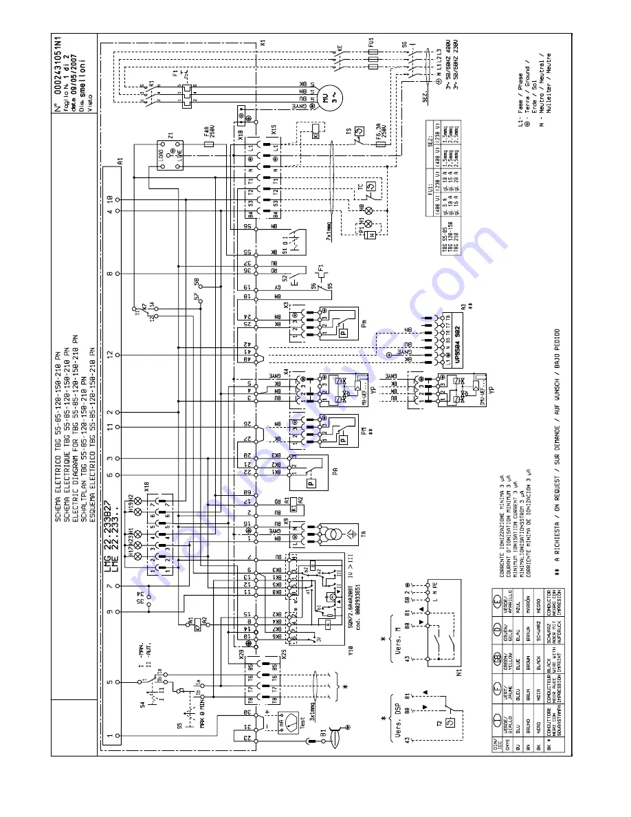
Page 5: ...djustment 37 Air regulation on the combustion head Maintenance Use of the burner 41 Problem Cause Solution 42 Electric diagram 69 NDICE P GINA Advertencias dirgidas al usuario 10 Caracteristicas tecni...
Page 6: ...e si dovesse traslocare e lasciare l apparecchio assicurarsi sempre che il libretto accompagni l apparecchio in modo che possa essere consultato dal nuovo proprietario e o dall installatore Per tutti...
Page 7: ...compromettere il buon funzionamento del bruciatore Per la prima messa in funzione dell apparecchio far effettuare da personale professionalmente qualificato le seguenti verifiche a il controllo della...
Page 8: ...the owner moves and leaves the equipment make sure that the booklet always goes with the equipment so it can be consulted by the new owner and or installer For all equipment with optionals or kits inc...
Page 9: ...law and regulations since incorrect installation may cause damage to person animals or things for which damage the manufacturer shall not can be held responsible Before installation it is advisable to...
Page 10: ...est siempre con el aparato para que pueda ser consultado por el nuevo propietario y o instalador Para todos los aparatos con elementos opcionales o kits incluidos los el ctricos hay que utilizar solo...
Page 11: ...comprometer el buen funcionamiento del quemador La primera vez que se pone en funcionamiento el aparato el personal cualificado profesionalmente tiene que controlar a la estanqueidad en el tramo inte...
Page 12: ...dernier toujours v rifier que la notice accompagne l appareil afin qu il puisse tre consulter par le nouveau propri taire et ou par l installateur Pour tous les appareils avec options ou kit y compris...
Page 13: ...v rifications suivantes par du personnel qualifi a le contr le de l tanch it de la partie interne et externe des tuyaux d arriv e du combustible b la r glage du d bit du combustible en fonction de la...
Page 14: ...VAZIONE FIAMMA FLAME DETECTOR DETECTION FLAMME DETECCION LLAMA SONDA DI IONIZZAZIONE IONISATION PROBE SONDE DE IONISATION SONDA DE IONIZACION RUMOROSITA NOISE NIVEAU DE BRUIT RU DO dBA 72 73 75 5 79 8...
Page 15: ...OLANTE ISOLATING GASKET 1 1 1 1 1 JUNTA JOINT ISOLANT PRIGIONIERI STUD BOLTS N 4 N 4 N 4 N 4 N 4 PERNO CON TOPE GOUJONS M 12 M 12 M 12 M 12 M 12 DADI EXAGONAL NUTS N 4 N 4 N 4 N 4 N 4 TURCAS ECROUS M...
Page 16: ...iento quemador 4 Dispositivo regulaci n cabeza 5 Bisagra 6 Brida acoplamiento rampa gas 7 Cuadro el ctrico 8 Motor 9 Servomotor regulaci n aire 1 Testa di combustione 2 Guarnizione 3 Flangia attacco b...
Page 17: ...sin ptico 10 Apparecchiatura 11 Pressostato aria 12 Trasformatore d accensione 13 Contattore motore 14 Rel termico 15 Spina 7 poli 16 Spina 4 poli 17 Pannello sinottico it en es 10 Bo tier de command...
Page 18: ...ottenuti su caldaie di prova rispondenti alla norma EN676 e sono orientativi per gli accoppiamenti bruciatore caldaia Per il corretto funzionamento del bruciatore le dimensioni della camera di combus...
Page 19: ...e disposti secondo quanto indicato nello schema Legenda 1 Valvola di intercettazione manuale 2 Giunto antivibrante 3 Filtro gas 4 Pressostato di minima pressione gas 5 Valvola di sicurezza 6 Regolator...
Page 20: ...Sono possibili diverse soluzioni di montaggio 8 8a 9 della rampa val vole come evidenziato nel disegno a fianco Scegliere la posizione pi razionale in base alla conforma zione del locale caldaia e all...
Page 21: ...il relativo pressacavo 3 Riposizionare la piastrina stringi cavi come da figura 3 Ruotare l eccentri co 6 in modo che la piastrina eser citi una adeguata pressione sui due cavi quindi stringere le vit...
Page 22: ...alvola pneumatica consente l incremento della portata di gas fino al valore massimo regolato Nel caso di assenza fiamma l apparec chiatura si arresta in blocco di sicurez za led 7 entro 3 secondi dall...
Page 23: ...operativo Tabella codici colore per indicatore luminoso multicolore LED Stato Codice colore Colore Tempo di attesa tw altri stati di attesa Spento Fase di accensione accensione controllata l l l l l...
Page 24: ...MIN minimo e MAN manuale L apparecchiatura di comando riceve cos tensione ed il programmatore determina l inserzione del bruciatore come descritto nel capitolo descri zione del funzionamento Nota La p...
Page 25: ...enza il bruciatore si arresta in blocco Per accertareilcorrettofunzionamen to del pressostato aria occorre con bruciatore al minimo dell erogazione aumentare il valore di regolazione fino a verificarn...
Page 26: ...un microamperometro di scala adeguata e far ripartire il bruciatore Una volta comparsa la fiamma sar possibile misurare il valore della corrente di ionizzazione il cui valore minimo per assicurare il...
Page 27: ...15 5 6 TBG 210PN 5 5 SCHEMA REGOLAZIONE ELETTRODI SONDA IONIZZAZIONE N 0002934691 REV 25 01 2006 Legenda 1 Elettrodo ionizzazione 2 Elettrodo accensione 3 Disco fiamma 4 Miscelatore 5 Tubo mandata gas...
Page 28: ...anda aria che N B Le regolazioni sopra esposte sono indicative posizionare la testa di combustione in funzione delle caratteristiche del focolare X Distanza testa disco regolare la distanza X seguendo...
Page 29: ...a 3 per un tratto sufficiente a garantire il successivo smontaggio del gruppo miscelazione Utilizzando la stessa chiave agire sullo snodo sferico 6 nella direzio ne indicata dalla freccia sganciando l...
Page 30: ...La tubazione del gas non stata adeguatamente sfogata dall aria caso di prima accensione 3 La pressione del gas insufficiente o eccessiva 4 Passaggio aria tra disco e testa troppo chiuso RIMEDIO 1 Inv...
Page 31: ...king fields are obtained from test boilers corresponding to the standard EN676 and are indicatively for the combina tion burner boiler For correct working of the burner the size of the combustion cham...
Page 32: ...turer The job of the installer The gas supply scheme is shown in the diagram below The gas train is certified in accordance with regulations EN 676 and is supplied separately from the burner A manual...
Page 33: ...tud bolts washers and the nuts provided 7 Note isolate completely with suitalbe materia the space between the burner tube and the hole on the refractory mate rial inside the boiler s shutter GAS TRAIN...
Page 34: ...exerts sufficient pressure on the two cables then tighten the screws that fasten the cable float Finally connect the two 7 and 4 pole plugs IMPORTANT the housings for the cables for the 7 and 4 pole p...
Page 35: ...opens the air damper and the pneumatic valve allows the gas supply to increase to its set maximum If there is no flame the control box stops in its safety lock out LED 7 within 3 seconds from the open...
Page 36: ...nks l l l l On Extraneous light when burner startup 5 blinks l l l l l On Time out LP LP is welded in working position 6 blinks l l l l l l On Free 7 blinks l l l l l l l On Too many losses of flame d...
Page 37: ...rry out the exchange the ignition transformer does not switch on and the valves for the ignition flame also do not switch with the result that the control box goes to lock out It should be pointed out...
Page 38: ...c control so the contact must be closed at rest fan stopped and so no air pressure in burner This condition is produced if the control box is not switched on and the burner stays stopped 18 The gas pr...
Page 39: ...nisation electrode 2 Ignition electrode 3 Deflector disk 4 Mixer 5 Gas outlet pipe N 0002934691 REV 25 01 2006 TBG 120P TBG 120PN TBG 120ME TBG 150P TBG 150PN TBG 150ME TBG 210P TBG 210PN TBG 210ME Mo...
Page 40: ...ulates the aspiration flow from the burner fan This must of course be the case when the burner is working at maximum desired supply N B The above adjustments are indicative only position the combustio...
Page 41: ...cessful disassembly of the mixing unit With the same wrench turn the ball joint 6 in the direction indicated with the arrow unhooking the lever that moves the combustion head forward figure 2 Slacken...
Page 42: ...n check its efficiency by inserting the analog micro ammeter 4 Check visually and using the instru ment 5 Restore the connection 6 Ensure that the boiler fumes passage and chimney connection are free...
Page 43: ...y son orien tativos para realizar los acoplamientos entre el quemador y la caldera Para que el quemador funcione correctamente las dimensiones de la c mara de combusti n tienen que ajustarse a la nor...
Page 44: ...a Leyenda 1 V lvula de corte manual 2 Manguito antivibraci n 3 Filtro de gas 4 Presostato de presi n m nima del gas 5 V lvula de seguridad 6 Regulador de presi n 7 Dispositivo de control de la estan q...
Page 45: ...QUEMADOR A LA CALDERA MONTAJE DE LA RAMPA DE GAS Existen varias posibilidades de montaje 8 8a 9 de la rampa de v lvulas como indica el dibujo de al lado Elija la posici n m s racio nal seg n la confor...
Page 46: ...na adecuada presi n en los dos cables y luego apretar los tornillos que sujetan la plaquita Por ltimo conectar las dos clavijas de 7 y 4 polos NOTA IMPORTANTE los alojamien tos de los cables para las...
Page 47: ...tica permite incrementar el caudal de gas hasta el valor m ximo regulado En caso de ausencia de llama la caja de control se para bloque ndose en condiciones de seguridad led 7 antes de 3 segundos desd...
Page 48: ...sici n operativa 6 parpadeos l l l l l l Encendido Encendido Non utilizado 7 parpadeos l l l l l l l Encendido Encendido Demasiadas p rdidas de llama durante el funcionamiento limitaci n de repeticion...
Page 49: ...n del funcio namiento Nota el prebarrido se efect a con el aire abierto y por lo tanto durante el mismo el servomotor de regulaci n se activa y realiza la carrera comple ta de apertura hasta el m xim...
Page 50: ...arse del correcto funcionamiento del presostato del aire hay que con el quemador al m nimo suministro aumentar el valor de regulaci n hasta comprobar que interviene con el inmediato paro de bloqueo de...
Page 51: ...s de un microamper metro de escala adecuada y volver a poner en mar cha el quemador Cuando aparece la llama ya se puede medir el valor de la corriente de ionizaci n cuyo valor m nimo para asegurar el...
Page 52: ...1 Electrodo de ionizaci n 2 Electrodo de encendido 3 Disco llama 4 Mezclador 5 Tubo ida gas N 0002934691 REV 25 01 2006 Mod A B C TBG 55PN 5 6 7 TBG 85PN 5 3 3 TBG 120PN 5 5 TBG 150PN 15 5 6 TBG 210PN...
Page 53: ...regula el flujo en la aspiraci n del venti Nota las regulaciones arriba indicadas son solo orientativas poner la cabeza de combusti n seg n las caracter sticas de la c mara de combusti n X Distancia e...
Page 54: ...ra que garantice el desmontaje suce sivo del grupo de mezcla Utilizando la misma llave actuar sobre la articulaci n esf rica 6 en la direcci n indicada por la flecha desenganchando la palanca de avanc...
Page 55: ...el electrodo y la masa no es correcta 6 Aislador sucio y por ello el electro dodescarga a masa 1 Relaci n aire gas incorrecta 2 No se ha purgado correctamenteel aire de la tuber a del gas en elcaso de...
Page 56: ...obtenus sur des chaudi res d essai r pondant la norme EN676 et sont indicatifs en ce qui concerne les accouplements br leur chaudi re Pour un fonctionnement correct du br leur les dimensions de la cha...
Page 57: ...ma L gende 1 Vanne de coupure manuelle 2 Joint antivibratoire 3 Filtre gaz 4 Pressostat de pression minimum de gaz 5 Vanne de s curit 6 R gulateur de pression 7 Dispositif de contr le de l tan ch it d...
Page 58: ...MONTAGE DE LA RAMPE A GAZ Diff rentes solutions de montage sont possibles 8 8a 9 de la ram pe vannes comme indiqu sur le dessin ci contre Choisir la position la plus rationnelle en fonction de la con...
Page 59: ...ad quate sur les deux c bles puis serrer les vis qui fixent la plaquette Enfin relier les deux fi ches 7 et 4 p les REMARQUE IMPORTANTE les lo gements des c bles pour les fi ches 7 et 4 p le sont pr...
Page 60: ...d bit de gaz jusqu la valeur maximale r gl e En cas d absence de flamme le bo tier de commande et de contr le s arr te en position de blocage de s curit voyant 7 dans un d lai de 3 secondes apr s l ou...
Page 61: ...teur lumineux multicolore LED Etat Code couleur Couleur Temps d attente tw autres tats d attente Eteint Phase d allumage allumage contr l l l l l l Jaune clignotante Fonctionnement flamme O K Vert Fon...
Page 62: ...IN minimum et MAN manuelle Le bo tier de commande re oit ainsi la tension et le program mateur d termine l activation du br leur comme d crit au chapitre de scription du fonctionnement Remarque La pr...
Page 63: ...teur d allumage ne se d clenche pas et les vannes du gaz ne s ou vrent pas par cons quent le br leur s arr te en situation de blocage Pour s assurer du fonctionnement correct du pressostat d air il es...
Page 64: ...o amp re m tre d chelle adapt e et red marrer le br leur D s l apparition de la flamme il sera possible de mesurer la valeur du courant de ionisation dont la valeur minimale pour garantir le fonctionn...
Page 65: ...de de ionisation 2 Electrode d allumage 3 Disque flamme 4 M langeur 5 Tuyau de d part gaz N 0002934691 REV 25 01 2006 Mod A B C TBG 55PN 5 6 7 TBG 85PN 5 3 3 TBG 120PN 5 5 TBG 150PN 15 5 6 TBG 210PN 5...
Page 66: ...ur la t te n cessitant une ouverture sensible du volet d air qui r gule le flux de l aspiration du ventilateur br leur N B Les r glages indiqu s ci dessus sont indicatifs positionner la t te de combus...
Page 67: ...e pour garantir le d mon tage successif du groupe de m lange En utilisant la m me cl intervenir sur l articulation sph rique 6 dans la direction indiqu e par la fl che en actionnant le levier d avance...
Page 68: ...lumage 3 La pression du gaz est insuffisan teou excessive 4 Passage trop troit de l REM DE 1 Invertir l alimentation c t 230V du transformateur d allumage etv rifier l aide d un microamp rem tre analo...
Page 69: ...67 69 0006081042_200705...
Page 70: ......
Page 71: ......
Page 72: ......
Page 73: ......
Page 74: ...La Casa por lo tanto se reserva cualquier posibilitad de modificati n de datos t cnicos y otras anotaciones Ce manuel rev t caract re purement indicatif La maison se reserve la possibilit de modifier...