N° 0002910950N1
8 / 26
0006081537_201311
ENGLISH
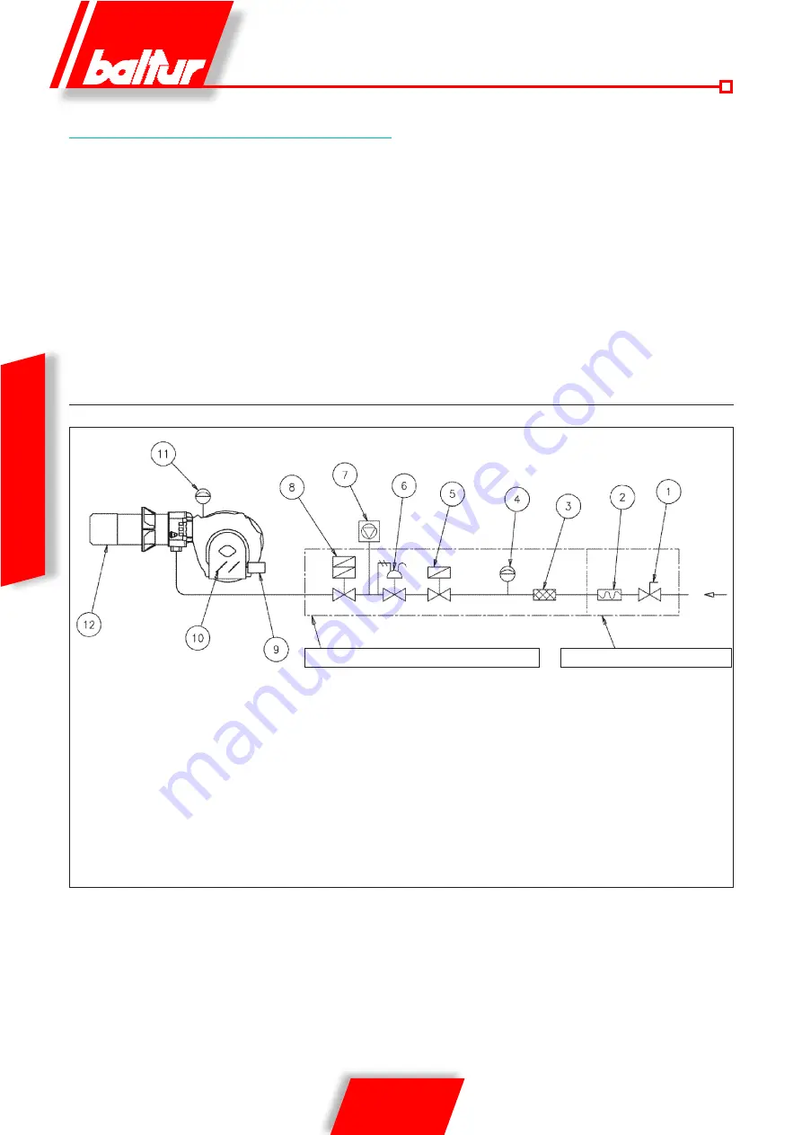
GAS SUPPLY LINE
The gas train is certified in accordance with Standard EN 676 and
is supplied separately from the burner.
a manual shut off valve and an anti-vibration joint must be
installed upstream of the gas valve, as shown in the diagram.
generaL gas Burner Diagram
1) Manual shut off valve
2) Anti-vibration joint
3) Gas filter
4) Minimum gas pressure switch
5) Safety valve
6) Pressure regulator
7) Valve seal control device (obligatory for burner with
maximum nominal thermal output over 1200 kW)
8) Pneumatic working valve
9) Control servomotor
10) Air adjustment gate
11) Air pressure switch
12) Combustion head
Gas train supplied by the manufacturer
Responsibility of the installer
Summary of Contents for TBG 80 LX PN V
Page 2: ......
Page 26: ...24 26 0006081537_201311 ENGLISH MINIMUM IONISATION CURRENT 3 μA OPTIONAL WIRING DIAGRAM ...
Page 28: ...26 26 0006081537_201311 ENGLISH ...
Page 54: ...26 26 0006081537_201311 ESPAÑOL ...
Page 80: ...26 26 0006081537_201311 FRANÇAIS ...
Page 104: ...24 26 0006081537_201311 TÜRKÇE ASGARİ İYONİZASYON AKIMI 3 µA TALEP ÜZERİNE ELEKTRİK ŞEMASI ...
Page 106: ...26 26 0006081537_201311 TÜRKÇE ...
Page 132: ...26 26 0006081537_201311 PYCCKИИ ...
Page 156: ...24 26 0006081537_201311 中 文 最小电离电流3μA 如果有需求 电气图 ...
Page 158: ...26 26 0006081537_201311 中 文 ...
Page 159: ......


