12 / 20
0006081531_201203
ion
iz_
BT
3x
x
ENGLISH
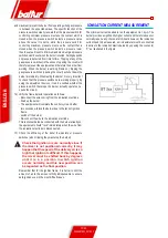
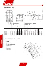
IONISATION CURRENT MEASUREMENT
The minimum current needed to run the equipment is 1.4 µA. The
burner provides a significantly higher current and therefore does not
normally require any checks at all. Should however, the ionisation
current need to be measured, a microammeter must be connected
in series to the ionisation electrode lead by opening the connector
“C” as illustrated in the figure.
and maximum) prevent the burner from operating when gas pressure
is between the expected values. The specific function of the
pressure switches clearly reveals that the pressure switch for
controlling minimum pressure must use the contact which is
closed when the pressure switch detects a pressure value
above the value it is set to, while the pressure switch for
controlling maximum pressure must use the contact that is
closed when the pressure switch detects a pressure lower
than the value it is set to. Minimum and maximum gas pressure
switches must be set when the burner is tested. Setting depends
on pressure detected from time to time. Tripping of any of the
gas pressure switches (in the sense of opening the circuit) will
therefore prevent the equipment and therefore the burner from
working. When the burner is working (flame on), tripping the
gas pressure switches (opening the circuit) will shut down the
burner immediately. When testing the burner, it is very important
to check that the pressure switches are working properly. By
using the adjustment devices, it can be verified whether the
pressure switch that stops the burner actually operates (i.e.
opens the circuit).
14) Verify the flame detector operation as follows:
- disconnect the wire coming from the ionisation electrode,
- Start up the burner;
- The equipment will complete the control cycle and after
two seconds will lock the burner due to the lack of ignition
flame;
- switch off the burner;
- Re-connect the wire to the ionisation electrode.
This test should also be conducted with the burner already on;
the equipment should "lock" immediately when the wire from
the ionisation electrode is disconnected.
15) Check the efficiency of the boiler thermostats or pressure
switches (when tripping they must stop the burner).
!
Check that ignition occurs normally since if
the mixer is not positioned correctly, it may
happen that the speed of the delivery air is so
high that ignition is difficult. If this happens,
the mixer must be shifted back by degrees
until it is in a position in which ignition
occurs normally, and this new position can
be regarded as the final position.
Remember that for the ignition flame, it is better to limit the
amount of air to the amount strictly indispensable to ensure
safe ignition even in the most difficult cases.
Summary of Contents for TBG 85 ME
Page 2: ......
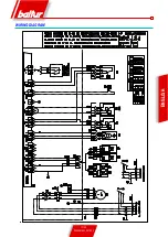
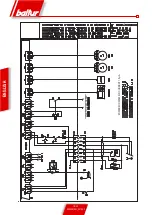
Page 19: ...17 20 0006081531_201203 ENGLISH WIRING DIAGRAM...
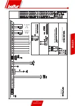
Page 20: ...18 20 0006081531_201203 ENGLISH START FOR RECORDER MINIMUM IONISATION CURRENT 1 5 A...
Page 39: ...17 20 0006081531_201203 ESPA OL ESQUEMA EL CTRICO...
Page 40: ...18 20 0006081531_201203 ESPA OL ARRANQUE PARA REGISTRADOR CORRENTE M NIMA DE IONIZACI N 1 5 A...
Page 59: ...17 20 0006081531_201203 FRAN AIS SCHEMA ELECTRIQUE...
Page 60: ...18 20 0006081531_201203 FRAN AIS MARCHE POUR ENREGISTREUR COURANT D IONISATION MINIMUM 1 5 A...
Page 79: ...17 20 0006081531_201203 T RK E ELEKTR K EMASI...
Page 80: ...18 20 0006081531_201203 T RK E REG LAT R N BA LATMA M N MUM YON ZASYON AKIMI 1 5 A...
Page 84: ...2 20 0006081531_201203 PYCCK BALTUR a b c a b c d e f g...
Page 85: ...3 20 0006081531_201203 PYCCK 2 RC a b c d e a b a b c d...
Page 89: ...7 20 0006081531_201203 PYCCK A 5 6 B 3 2 C 4 1 7 8 8a 9 DN65 DN80 A B 10 C 11...
Page 90: ...8 20 0006081531_201203 N 0002910950n2 PYCCK EN676 1 2 3 4 5 6 7 8 9 10 11 12 13 14...
Page 94: ...12 20 0006081531_201203 ioniz_BT3xx PYCCK 1 4 A 13 14 15...
Page 99: ...17 20 0006081531_201203 PYCCK...
Page 100: ...18 20 0006081531_201203 PYCCK 1 5 A...
Page 101: ...19 20 0006081531_201203 PYCCK 0 4 20 A...
Page 104: ...2 20 0006081531_201203 a b c a b c d e f g I...
Page 105: ...3 20 0006081531_201203 2 RC a b c d e a b a b c d I...
Page 109: ...7 20 0006081531_201203 5 6 2 3 7 4 1 8 8A 9 DN65 DN80 10 11...
Page 110: ...8 20 0006081531_201203 N 0002910950n2 EN676 1 2 3 4 5 6 7 8 9 10 11 12 13 14...
Page 113: ...11 20 0006081531_201203 display lamtec BT3xx 3 4 1 2 5 1 2 3 4 5 O BT3xx BT 3xx 200 CO...
Page 114: ...12 20 0006081531_201203 ioniz_BT3xx 1 4 A...
Page 117: ...15 20 0006081531_201203 figura 1 figura 2 figura 4 figura 3 2 2 1 3 4 5 8 6 8 9 0002934691 7 2...
Page 119: ...17 20 0006081531_201203...
Page 120: ...18 20 0006081531_201203 1 5 A...
Page 121: ...19 20 0006081531_201203 0 4 20 mA...
Page 123: ......


