15 / 20
0006081531_201203
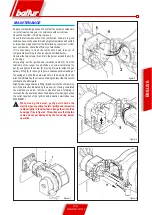
figura 1
figura-2
figura-4
figura-3
ENGLISH
MAINTENANCE
Analyse combustion gases and check that the emission values are
correct at least once a year, in compliance with current law.
Check the fuel filter: if it is dirty, replace it.
Check that all components of the combustion head are in good
condition, have not been deformed by high temperatures and contain
no impurities or deposits from the installation environment or from
poor combustion; check the efficiency of electrodes.
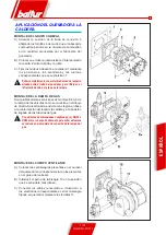
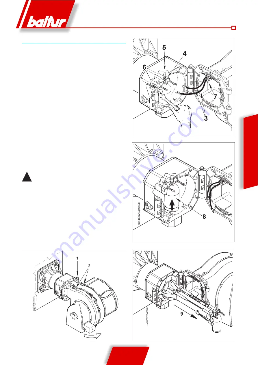
If it is necessary to clean the combustion head, take out its
components according to the procedure described below:
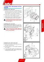
Unscrew the two screws (2) and turn the burner around the pin (1)
in the hinge.
After pulling out the ignition and ionisation cables (3) from the
terminals of the respective electrodes, unscrew completely the
nut (4) and tighten the screw (5), moving it forward inside the gas
delivery fitting (8) far enough to permit subsequent dismantling of
the mixing unit. With the same wrench turn the ball joint (6) in the
direction indicated by the arrow, unhooking the lever that moves the
combustion head forward.
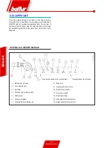
Slightly raise the gas delivery fitting (8) and remove the entire mixing
unit in the direction indicated by the arrow (9). Having completed
the maintenance works, refit the combustion head, following in
reverse order the operations described above, after having checked
the correct position of the ignition and ionisation electrodes (see
0002934691).
!
When closing the burner, gently pull towards the
electrical panel, putting the two ignition and ionisation
cables slightly in tension, then arrange them into their
housings (7) as in figure 2. This will ensure that the two
cables do not get damaged by the fan during burner
operation.
Summary of Contents for TBG 85 ME
Page 2: ......
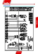
Page 19: ...17 20 0006081531_201203 ENGLISH WIRING DIAGRAM...
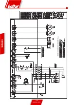
Page 20: ...18 20 0006081531_201203 ENGLISH START FOR RECORDER MINIMUM IONISATION CURRENT 1 5 A...
Page 39: ...17 20 0006081531_201203 ESPA OL ESQUEMA EL CTRICO...
Page 40: ...18 20 0006081531_201203 ESPA OL ARRANQUE PARA REGISTRADOR CORRENTE M NIMA DE IONIZACI N 1 5 A...
Page 59: ...17 20 0006081531_201203 FRAN AIS SCHEMA ELECTRIQUE...
Page 60: ...18 20 0006081531_201203 FRAN AIS MARCHE POUR ENREGISTREUR COURANT D IONISATION MINIMUM 1 5 A...
Page 79: ...17 20 0006081531_201203 T RK E ELEKTR K EMASI...
Page 80: ...18 20 0006081531_201203 T RK E REG LAT R N BA LATMA M N MUM YON ZASYON AKIMI 1 5 A...
Page 84: ...2 20 0006081531_201203 PYCCK BALTUR a b c a b c d e f g...
Page 85: ...3 20 0006081531_201203 PYCCK 2 RC a b c d e a b a b c d...
Page 89: ...7 20 0006081531_201203 PYCCK A 5 6 B 3 2 C 4 1 7 8 8a 9 DN65 DN80 A B 10 C 11...
Page 90: ...8 20 0006081531_201203 N 0002910950n2 PYCCK EN676 1 2 3 4 5 6 7 8 9 10 11 12 13 14...
Page 94: ...12 20 0006081531_201203 ioniz_BT3xx PYCCK 1 4 A 13 14 15...
Page 99: ...17 20 0006081531_201203 PYCCK...
Page 100: ...18 20 0006081531_201203 PYCCK 1 5 A...
Page 101: ...19 20 0006081531_201203 PYCCK 0 4 20 A...
Page 104: ...2 20 0006081531_201203 a b c a b c d e f g I...
Page 105: ...3 20 0006081531_201203 2 RC a b c d e a b a b c d I...
Page 109: ...7 20 0006081531_201203 5 6 2 3 7 4 1 8 8A 9 DN65 DN80 10 11...
Page 110: ...8 20 0006081531_201203 N 0002910950n2 EN676 1 2 3 4 5 6 7 8 9 10 11 12 13 14...
Page 113: ...11 20 0006081531_201203 display lamtec BT3xx 3 4 1 2 5 1 2 3 4 5 O BT3xx BT 3xx 200 CO...
Page 114: ...12 20 0006081531_201203 ioniz_BT3xx 1 4 A...
Page 117: ...15 20 0006081531_201203 figura 1 figura 2 figura 4 figura 3 2 2 1 3 4 5 8 6 8 9 0002934691 7 2...
Page 119: ...17 20 0006081531_201203...
Page 120: ...18 20 0006081531_201203 1 5 A...
Page 121: ...19 20 0006081531_201203 0 4 20 mA...
Page 123: ......

